User:Vilimaka/Transparent Rings Atomic Model
| Work in progress, expect frequent changes. Help and feedback is welcome. See discussion page. |
| Home | TRAM | 3D Periodic trends | Climate change education curriculum | Teaching Primary School Science | Teaching Science in the Secondary School classroom | My Sandbox | My L4C course home page| |
Today's date: 28 February 2025
Contents
Transparent Rings Atomic Model (TRAM)
What is TRAM?
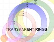
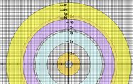
The Transparent Rings Atomic Model (or TRAM) is a teaching model that can be used to help students visualise atomic energy levels and understand the electronic structure of the atom in a meaningful way. TRAM can help students develop a better understanding of atomic orbitals and how to write electron configuration using the spdf notation.
The rings of TRAM are can be drawn using MS Word of MS Powerpoint. These two MS programs can ensure that the colour of each ring is made transparent (as shown in the diargam on the left) by following the instructions provided in the Construction of TRAM section below.
Once the rings are drawn, they can be printed (or photocopied) on OHP transparencies, one ring per sheet of transparency. Uncoloured rings can be used by groups of students while the teacher demonstrates with the coloured rings.
Why use TRAM?
Students of chemistry often find it difficult to write the electron configuration of atoms with large atomic numbers. From years of experience teaching Form 7 (New Zealand Bursary and USP Foundation) chemistry, I found that students begin to make these mistakes when electrons are put into the 4th energy level. Below are examples of wrong electron configurations that many students write:
| Element | Wrong electron configuration | Instead of (right electron configuration |
|---|---|---|
| Potassium (Z = 19) | 1s2 2s2 2p6 3s2 3p6 3d1 |
1s2 2s2 2p6 3s2 3p6 4s1 |
| Scandium (Z = 21) |
1s2 2s2 2p6 3s2 3p6 3d3 |
1s2 2s2 2p6 3s2 3p6 4s2 3d1 |
Research carried out with a class of science student-teachers show that this misconception also exists in the university chemistry classroom.
Possible causes of errors
What would be some possible causes of the error shown in the table above?
Orbits or orbitals?
One possible cause of the above error is the miscopnception that electrons are in orbits - similar to the orbits of the planets around the sun.
When the basic structure of the atom is taught in many classrooms, it is common to hear the phrase 'electrons in their orbits'. However, to say that electrons are in orbits would mean that one can be certain of the whereabout of an electron at any particular instant. This common misconception is contrary to the Heisenberg Uncertainty Principle.Instead of occupying defintie orbits, electrons occupy definite energy levels, and in each energy level, they move around in definite 'regions of space' called orbitals. In any particular instant, a single electron is most likely to be found in this region of space (i.e. the orbital). Since electrons are negatively charged, they tend to spend most of their time in the region of their orbital which is closer to the positively charged nucleus (opposite charges attract).
The sooner for teachers to use the right word (i.e. orbitals) the sooner would be for students to construct a more meaningful understanding of the electronic structure of the atom. The use of the word orbital in classroom instruction gives it a probalistic flavour. The concept of electron density provides the probability that an electron will be found in any region of space in the atom.
Equally spaced orbits
Related to the above 'solar-system model' (a misconception) is the erroneous belief that the orbits are equally spaced.
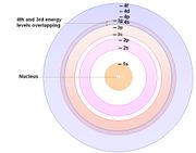
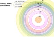
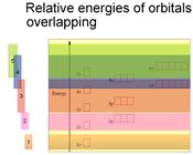
Adjacent energy levels are not equally spaced from one another. Instead, the further an energy level is from the nucleus the closer it is to adjacent levels. As a result, there is overlapping of energy levels - beginning from the 3rd and 4th energy levels. View this Slideshow.
Traditional Algorithm
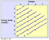
The 'zigzag' algorithm (pictured below) is the common tool that teachers use to teach students how to write electron configuration in the spdf notation. Unfortunately, however, this algorithm does not effectively show students where atomic orbitals overlap. Poor teaching skills, coupled with a patchy content knowledge of chemistry, mean that the benefit of this algorithm as a teaching aid cannot go beyond the examination venue.When students are able to visualise the energy levels overlappings (described earlier), they would then be able to understand why it is important to follow the traditional 'zigzag' algorithm when writing electron configurations using the spdf notation. This page in Wikipedia contains a good version of the zigzag alogirthm.
Constructing TRAM
Computer enhanced TRAM. This can be prepared by doing the following:
Step 1: Open a Word document, and ensure that the Drawing tools are activated by clicking on the Drawing icon on the Main Toolbar. See the diagram below.
Step 2: When the Drawing tools are activated, the Drawing toolbar appears at the bottom of the screen (as show below).
Step 3: Click Draw and select Grid and type in 2mm for both Horizontal and Vertical spacing. On the dialogue box the appears, tick Snap object to grid, Use grid marginand Display grid line on screen .
Step 4: Use the Line tool to draw 2 lines: one vertical and one hirizontal at the centre of the grid. Where the two lines intersect is the centre of all circles that you'll draw.
Step 5: To draw the rings, click AutoShapes, then Basic Shapes and then the Donut.
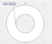
Step 6: Draw a donut. Centre it and then resize the diameters of both circles to your desired measurements. To resize the outer circle: right-click on the donut, select Format AutoShape, click on the Size tab, and type in the desired diameter (in millimeters) for both Height and Width. To resize the inner circle, put the pointer on the small yellow diamond (see diagram on the left) and adjust, using the grid with its 2 mm2 squares as reference.Step 7: Select the donut (by clicking it) and use the Fill Colour toolto fill the donut with a colour of your choice.
Step 8: Make the donut colour transparent. While it is still selected, right click, go to Format AutoShape and set the transparency (to 60%, for example).
Step 9: Label the circle. To do this, create a small Text Box and type in the label (e.g. 1s). Remove the outline of the box by selecting the text box, open the Line Colour menu
and then click on No Line. Move (click and drag) the label into position in the circle. Make small adjustments by holding down the keyboard Control key and pressing the arrow keys on your keyboard.
Step 10: Draw other donuts (rings) to represent the other energy levels.
Step 11: Once you have drawn all the rings, remove the drawing grid. To do this, click Draw, and select Grid, and remove the tick from Display gridlines on screen.
Step 12: Finally, group the TRAM. Click on the Select object tool (white arrow) in the Draw toolbar, take your cursor to the top left hand corner of an imaginary square around the TRAM (as shown below), hold the left-mouse down and move diagonally to the opposite corner of the imaginary square. This selects everything inside the square. Open the Draw menu and select Group. All parts of the TRAM will now remain together.
Using TRAM as an instructional tool
Activity 1: Diagnosing misconceptions
Activity 2: Students exploration of TRAM
| Prepare the coloured transparent rings in advance, and prepare a MS Powerpoint to help you explain the main ideas. You also prepare a second set of rings that are not coloured for your students to use (see diagram below). Photocopy these rings onto OHP transparencies - one ring (energy level) per transparency. Each set of rings concists of a 1st energy level ring, a 2nd energy level ring, a third energy level ring, a 4th energy level ring, etc. Copy enoungh sets of rings for your students whom you have assigned into small working groups of 3 or 4.Grouping your students not only would encourage active participation and discussion but you would also be saving on the costs of resources. Instruct students to arrange the rings as shown in the diagram below.
This Slideshow will give you some ideas. |
Activity 3: Making connections
Before using the ‘zigzag’ algorithm, use the rings to teach the energy levels, and the order in which electrons are assigned into orbitals. Draw the students’ attention to the areas of overlapping orbitals.
|
