Sinusoidal Oscillator

|
Sinusoidal Oscillator |
- Introduction
- Objectives
- Block Diagram of Oscillator
- Principle of Oscillators
- How Oscillations are initiated at First?
- Sinusoidal Oscillators
- Classification of Sinusoidal Oscillators
- Details of RC Oscillators with Examples
- Circuit Diagram
- Circuit Operation
- Formulae
- Circuit Diagram
- Let Us Sum Up
- Glossary
- References and Further Readings
- Answers to Self-Assessment Questions

|
Introduction |
In the previous unit, you studied the concept of positive feedback and the effect of positive feedback on the gain of transistor amplifier. The present unit is a discrete unit but depends on the concept of positive feedback from the previous unit you have studied in this course.
In electronics, can you imagine a circuit that produces desired output waveforms without any external input signal? Does it sound possible? Yes, in practice, oscillators are circuits that produce periodic waveforms.
In oscillators, the only input requirement is of DC power supply which is required for operation of the active device. The frequency of the generated waveforms may vary from a few Hz to several KHz. It may be used to generate AC waveforms such as sinusoidal, rectangular or sawtooth depending upon the type of oscillators used. They have wide range of applications such as in radios, Televisions, communication systems, computers, industrial controlled applications, and laboratories, as a function or signal generator. We can say that without oscillators very few electronic circuits would be possible. Therefore, in this unit, we are going to learn about oscillators in detail.
| Block Diagram of Oscillator |
Before explaining the block diagram of an oscillator, let us recall the concept of positive feedback amplifier. All of you know that positive feedback amplifier consists of amplifier having gain of ‘A’ and feedback circuit with gain of ‘β’. Here, a part of output is fed back to input through feedback circuit. The signal which is fed back is added to the input signal using summer ‘[math]\Sigma [/math]
’ and output of the summer acts as an actual input signal to the amplifier.
The figure shows the block diagram of the oscillator. The difference between positive feedback amplifier and oscillator is that, in oscillator, there is no need of external input signal. To start the oscillations, output signal must be fed back in proper magnitude and phase.
<flash>file=blockdiagram.swf|width=70%|height=300|quality=best|</flash>
Fig: Blockdiagram of Oscillator
![]() For Replay click again on 'Click here to Start Animation'
For Replay click again on 'Click here to Start Animation'
| Principle of Oscillators |
An oscillator consists of an amplifier and a feedback network. Now, let us see which basic components are required to obtain oscillations.
- 'Active device' either Transistor or Op Amp is used as an amplifier.
- 'Feedback circuit' with passive components such as R-C or L-C combinations .
To start the oscillation with the constant amplitude, positive feedback is not the only sufficient condition. Oscillator circuit must satisfy the following two conditions known as Barkhausen conditions:
1. The first condition is that the magnitude of the loop gain (Aβ) must be unity. This means the product of gain of amplifier 'A' and the gain of feedback network 'β' has to be unity.
2. The second condition is that the phase shift around the loop must be 360° or 0°. This means, the phase shift through the amplifier and feedback network has to be 360° or 0°.
| How Oscillations are initiated at First? |
We have stated that oscillators do not require any external input. This means an oscillator's output feeds its own input and it must satisfy the two essential conditions to start oscillations. Here, you might be eager to know, from where the starting voltage comes. All of you are aware that every resistor has certain free electrons. At room temperature these free electrons move randomly and generate a noise voltage across the resistor due to collisions. This voltage is also known as thermal noise voltage. Hence, the resistor acts as small ‘ac’ voltage source. When power supply is turned on, for the first time this small ac noise voltage gets amplified and appears at the output terminal. This amplified output is applied to feedback circuit and output of feedback circuit is fed back to the amplifier as an input. It is again amplified by amplifier and fed back to input through feedback circuit. This process is repeated and at one particular frequency, circuit satisfies the necessary conditions to start oscillation. Using proper feedback components, it is possible to select the particular frequency.
<flash>file=how_oscillations_start.swf|width=70%|height=300|quality=best|</flash>
Fig: How Oscillations are initiated
![]() For Replay click again on 'Click here to Start Animation'
For Replay click again on 'Click here to Start Animation'
| Sinusoidal Oscillators |
The name sinusoidal oscillator itself indicates the meaning that this oscillator produces sine wave output.
For any type of circuit to behave as an oscillator, first it must satisfy the necessary and sufficient condition which is mentioned in the previous section. Depending upon the variation in the output waveform amplitude, there are two types of oscillations.
1. Damped
2. Undamped or (sustained)
Damped oscillations: Oscillations, whose amplitude goes on decreasing or increasing continuously with time, are called damped oscillations.
If amplitude of oscillations is decreasing continuously, it is known as underdamped. Whereas if amplitude of oscillations is increasing continuously, it is known as overdamped.
Undamped oscillations: Oscillations, whose amplitude remains constant with time, are called undamped oscillations or sustain oscillations.
Practical Oscillators
In practice, to obtain the sustained oscillations at desired frequency of oscillations, oscillator circuit must satisfy some of the basic requirements such as,
- Circuit must have positive feedback
- When positive feedback is used in the circuit, the overall circuit gain is given by,
[math]A_f = \frac{A}{1-A \beta}[/math]
This equation indicates that if ‘Aβ’ is equal to 1 only then overall gain becomes infinity. This means, there is output without any external input. In reality, to get sustained oscillations, at the first time when the circuit is turned on, the loop gain must be slightly greater than one. This will ensure that oscillations build up in the circuit. However, once a suitable level of output voltage is reached, the loop gain must decrease automatically to unity. Only then the circuit maintains the sustained oscillation. Otherwise, the circuit operates as over damped. This can be achieved in the circuit either by decreasing amplifier gain A or decreasing the feedback gain β.
<flash>file=sinuosci.swf|width=60%|height=300|quality=best|</flash>
Fig: Types of Oscillator
![]() For Replay click again on 'Click here to see Types of Oscillation'
For Replay click again on 'Click here to see Types of Oscillation'
| Classification of Sinusoidal Oscillators |
The name sinusoidal oscillator itself indicates that, this oscillator produces sine wave output. In the previous section, we had mentioned that the frequency of oscillation is determined by the feedback circuit components. Hence, according to the frequency determined components, there are three basic types of oscillators such as RC oscillator, LC oscillator and crystal oscillator.
1. RC oscillators: They use a resistance-Capacitance network to determine the oscillator frequency. They are suitable for low (audio range) and moderate frequency applications (5Hz to 1MHz). They are further divided as,
- RC phase shift oscillator
- Wien bridge oscillator and
- Twin-T oscillator
- RC phase shift oscillator
2. LC oscillators: Here, inductors and capacitors are used either in series or parallel to determine the frequency. They are more suitable for radio frequency(1 to 500 MHz) and further classified as,
- Hartley
- Colpitts
- Clapp and
- Armstrong oscillators
- Hartley
3. Crystal oscillator: Like LC oscillators it is suitable for radio frequency applications. But it has very high degree of stability and accuracy as compared to other oscillators.

|
Self-Assessment Questions (SAQs)- 5 |
|
Note: 1. List out the sinusoidal oscillators with their frequency range. | |
| Details of RC Oscillators with Examples |
We had seen the block diagram of oscillator. It consists of amplifier having gain of 'A' and feedback circuit with gain of 'β'. In case of RC oscillators, feedback circuit uses a Resistance-Capacitance combination.
This RC combination performs the dual function. It acts as feedback network as well as frequency determining network of the oscillator.
Principle of RC oscillators:
All of you know that a transistor in CE configuration acts as an amplifier or you can use Op Amp as an inverting amplifier. It not only amplifies the input signal but also shifts its phase by 180º. However, to produce oscillations, we must have positive feedback of sufficient amount. Positive feedback occurs only when the fed back voltage is in phase with the original input signal. This condition can be achieved in two ways.
1. Wien Bridge Oscillator
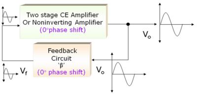
-360° or 0° phase shift by amplifier and 0° or 360° phase shift by feedback circuit
Fig:Principle of Wien Bridge Oscillator
One way of getting phase shift of 360º is to use two stages of amplifiers, each giving phase shift of 180º, or use noninverting amplifier using Op Amp. In this case, feedback signal does not produce any further phase shift. This is the basic principle of a Wien bridge oscillator.
2. RC Phase Shift Oscillator
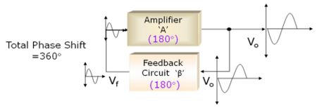
- 180° phase shift by amplifier and additional 180° phase shift by feedback circuit
Fig:Principle of RC Phase Shift Oscillator
Here we can take a part of output and pass it through a phase shift network (feedback circuit) giving additional phase shift of 180º. Thus, we get total phase shift of 180º + 180º = 360º as signal passes through the amplifier and the phase shift network. This is the basic principle of RC phase shift oscillator.

|
Self-Assessment Questions (SAQs)- 6 |
|
Note:
Answer the following question below by identifying the correct answers: 2. In RC phase shift oscillator, the feedback network produces ……. phase shift Answer the following True or False question 3. Wien bridge oscillator can be designed either using two stages of transistorized amplifiers or using noninverting amplifier using Op Amp. | |
The scope of this unit is restricted to Wien Bridge Oscillators; Let us study Wien Bridge Oscillators in detail:
| Circuit Diagram |
a) Lead-Lag circuit
The given circuit shows the RC combination used in Wien bridge oscillator. This circuit is also known as lead-lag circuit. Here, resistor [math]R_1[/math] and capacitor [math]C_1[/math] are connected in the series while resistor [math]R_2[/math] and capacitor [math]C_2[/math] are connected in parallel. We have to see how this circuit selects only one particular frequency.
How lead-lag circuit works?
Let us see what would be the output voltage at high frequencies.
Suppose, AC input signal 'Vi' is applied to this circuit, then what would be the output voltage? Here, the magnitude of the output Vo depends on the frequency of the input signal. How does it happen? You know that the reactance of the capacitor is inversely proportional to the frequency.
At high frequencies, the reactance of capacitor [math]C_1[/math] and [math]C_2[/math] approaches zero. This causes [math]C_1[/math] and [math]C_2[/math] appears short. Here, capacitor [math]C_2[/math] shorts the resistor [math]R_2[/math]. Hence, the output voltage Vo will be zero since output is taken across [math]R_2[/math] and [math]C_2[/math] combination.
In short, at high frequencies, circuit acts as a 'lag circuit'.
Let us see what would be the output voltage at low frequencies.
Similarly, at low frequencies, both capacitors act as open because capacitor offers very high reactance. Again output voltage will be zero because the input signal is dropped across the [math]R_1[/math] and [math]C_1[/math] combination. Here, the circuit acts like a 'lead circuit'.
What would happen if the input signal frequency is in between these two extremes?
Basically, lead-lag circuit acts like a resonant circuit. We have seen that, at two extremes, we get zero output voltage. But at one particular frequency between the two extremes, the output voltage reaches to the maximum value. At this frequency only, resistance value becomes equal to capacitive reactance and gives maximum output. Hence, this particular frequency is known as resonant frequency or oscillating frequency.
<flash>file=leadlag.swf|width=65%|height=380|quality=best|</flash>
Fig: Lead-Lag Circuit
![]() For Replay click again on 'Click here to Start Animation'
For Replay click again on 'Click here to Start Animation'
Here, one may ask, 'How to calculate this particular frequency?’ It is very simple. The maximum output would be produced if R = Xc.
Suppose, [math]R_1[/math] = [math]R_2[/math] = R and [math]C_1[/math] = [math]C_2[/math] = C, as you know that [math]Xc = \frac{1}{2{\Pi}f\,}[/math]
This gives resonant frequency [math]f = \frac{1}{2{\Pi}R\,C\,}[/math].
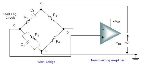
b) The given circuit shows Wien bridge oscillator using lead-lag circuit. Let us see why the name Wien bridge is given. The basic version of Wien bridge has four arms. The two arms are purely resistive and other two arms are frequency sensitive arms. These two arms are nothing but the lead-lag circuit about which we have already discussed. The series combination of [math]R_1[/math] and [math]C_1[/math] is connected between terminal a and d. The parallel combination of [math]R_2[/math] and [math]C_2[/math] is connected between terminal d and c .
To design oscillator circuit using this bridge, the output of bridge is given to the amplifier stage. Here, noninverting amplifier stage is used to achieve oscillations.
Fig: Circuit Diagram of Wien Bridge Oscillator
Can you guess why noninverting amplifier is required? For that, just recall the necessary condition of oscillations. To start the oscillations, the total phase shift of the circuit must be 360° and the magnitude of the loop gain must be greater than one.
Here, bridge does not provide phase shift at oscillating frequency as one arm consists of lead circuit and other arm consists of lag circuit. There is no need to introduce phase shift by an amplifier. Therefore, noninverting amplifier is used.

|
Self-Assessment Questions (SAQs)- 7 |
|
Note: 1. Explain term lead and lag circuit and its working principle. Answer the following question below by identifying the correct answers: 3. A lag circuit has a phase angle that is 4. A coupling circuit is also referred as….. | |
| Circuit Operation |
For better understanding of the Wien bridge oscillator, the same circuit can be redrawn as shown below. Observe the circuit diagram carefully. The lead lag circuit is used as feedback network about which we have already discussed. Here, noninverting amplifier stage is used to achieve oscillations.
The wien bridge oscillator circuit consists of two feedbacks, positive as well as negative.
A positive feedback is between output and noninverting terminal and a negative feedback is between the output and inverting terminal of OPAMP.
You know that for oscillator, positive feedback is essential. Here, positive feedback is used to produce zero degree phase shift between amplifier and feedback network.
Perhaps you would like to know why negative feedback is required here. To ensure sustained oscillations, the loop gain must be slightly greater than one when circuit is turned on for the first time. For Wien bridge oscillator, the gain of the amplifier must be greater than three (A>3), which will ensure that sustained oscillations build up in the circuit. Hence, to set this gain negative feedback is essential.
In practice, to obtain the sustained oscillations at the desired frequency of oscillations, the product of the voltage gain A and the feedback gain β must be one or greater than one. In this case, the amplifier gain A must be 3.
Hence, to satisfy the product condition, feedback gain β must be 1/3. Here, the gain of the noninverting amplifier is decided by resistor '[math]R_3[/math]' and '[math]R_4[/math]'.
For sustained oscillations, resistor '[math]R_4[/math]' must be twice of resistor '[math]R_3[/math]'.
Similarly, we get the maximum output Vo only if resistive value is equal to reactance value. Hence, the frequency of oscillation is decided by resistor 'R' and capacitor 'C'.
<flash>file=WBO circuit.swf|width=60%|height=300|quality=best|</flash>
Fig: Circuit Diagram of Wien Bridge Oscillator
![]() For Replay click again on 'Click here to Start Animation'
For Replay click again on 'Click here to Start Animation'
What happens if resistor [math]R_3[/math] is not equal to twice of resistor [math]R_4[/math]?
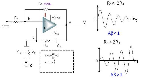
In the previous section we had seen that the value of resistor [math]R_3[/math] and [math]R_4[/math] plays a very important role. To start the oscillations, the resistor [math]R_3[/math] must be twice of the resistor [math]R_4[/math]. What happens if resistor [math]R_3[/math] is not equal to twice of resistor [math]R_4[/math]? If [math]R_3[/math] is less than 2[math]R_4[/math], the Aβ product will be less than unity and oscillations cannot be maintained. And if [math]R_3[/math] is greater than 2[math]R_4[/math], the gain significantly increases. Therefore, the product Aβ becomes very large. This will start the oscillations. But due to excessive gain, distortion may result.
Fig: Effect of [math]R_3[/math] and [math]R_4[/math] in Wien Bridge Oscillator
This indicates that some form of gain reduction is required at higher output voltage. One of the possible ways is to replace resistor [math]R_4[/math] by tungsten lamp. How this circuit works if resistor [math]R_4[/math] by tungsten lamp, is left to the student for further study of this topic.

|
Self-Assessment Questions (SAQs)- 8 |
|
Note: 1. Discuss the working of wien bridge oscillators with neat block diagram. Answer the following question below by identifying the correct answers: 4. In Wien-bridge oscillator, the gain of amplifier must be…… | |
| Formulae |
In practice, to obtain the sustained oscillations at the desired frequency of oscillations, the product of the voltage gain A and the feedback gain β must be one or greater than one. In this case, the amplifier gain A must be 3. Hence, to satisfy the product condition, feedback gain β must be 1/3.
How to select the component values to set the desired sustained oscillation frequency?
1. Gain components selection
For noninverting amplifier, gain is given by,
[math]A = 1 + \frac{R_3}{R_4}[/math]
Here, the gain of the noninverting amplifier is decided by resistor [math]R_3[/math] and [math]R_4[/math]
This gives, [math]R_4 = 2 R_3\, [/math] -------(1)
For sustained oscillations, resistor [math]R_4[/math] must be twice of resistor [math]R_3[/math].
2. Frequency components selection
We get the maximum output Vo only if resistive value is equal to reactance value. Hence, the frequency of oscillation is decided by resistor R and capacitor C. Actually, the oscillation frequency is given by equation no 2.
For maximum output, [math]R = X_c\, [/math] -------(2)
To simplify, if you keep values of resistance [math]R_1[/math] and [math]R_2[/math] same, and values of capacitors [math]C_1[/math] and [math]C_2[/math] same, then the frequently of lead – lag circuit is given by equation 3.
[math]f = \frac{1}{2{\Pi}\sqrt{R_1\,R_2\,C_1\,C_2}}[/math]
If [math]R_1 = R_2 = R\, [/math] and [math]C_1 = C_2 = C\, [/math] then
[math]f = \frac{1}{2{\Pi}R\,C\,}[/math] ------(3)

|
Self-Assessment Questions (SAQs)- 9 |
|
Note: 1. Explain how to select gain and frequency component of Wien bridge oscillator. Answer the following question below by identifying the correct answers: 3. How many resistors to be varied to change the frequency of a Wien bridge oscillator. | |

|
Critical Thinking Question |
|
Give in detail the technique used to reduce the loop gain at higher output voltage. | |

|
Results |

|
Glossary |
- Oscillator
Generates output signal with constant amplitude and desired frequency
- Loop gain
Product of the closed loop gain of amplifier (A) and the gain of feedback circuit ( β)
- Phase shift
Difference between the phase angle of the two waveforms
- Lag circuit
The output voltage lags the input voltage. At very high frequency, the phase angle ‘f’ becomes -90°.
- Lead circuit
The output voltage leads to input voltage. At very high frequency the phase angle ‘f’ becomes +90°.
| To get Answers to Self-Assessment Questions (SAQs)- click on the next button |
|


