Welcome to the Multimedia Course: Multimedia System Standards
OER initiative for Building Collabrative Learning for Multimedia
Broadband
ATM
Asynchronous Transfer Mode: It is a network technology based on transferring data in cells or packets of a fixed size. The cell used with ATM is relatively small compared to units used with older technologies. The small, constant cell size allows ATM equipment to transmit video, audio, and computer data over the same network, and assure that no single type of data hogs the line.
Some people think that ATM holds the answer to the Internet bandwidth problem, but others are skeptical. ATM creates a fixed channel, or route, between two points whenever data transfer begins. This differs from TCP/IP, in which messages are divided into packets and each packet can take a different route from source to destination. This difference makes it easier to track and bill data usage across an ATM network, but it makes it less adaptable to sudden surges in network traffic.
When deciding ATM service, you generally have a choice of four different types of service:
- Constant Bit Rate (CBR): specifies a fixed bit rate so that data is sent in a steady stream. This is analogous to a leased line.
- Variable Bit Rate (VBR): provides a specified throughput capacity but data is not sent evenly. This is a popular choice for voice and videoconferencing data.
- Available Bit Rate (ABR): provides a guaranteed minimum capacity but allows data to be bursted at higher capacities when the network is free.
- Unspecified Bit Rate (UBR): does not guarantee any throughput levels. This is used for applications, such as file transfer, that can tolerate delays.
Asynchronous Transfer Mode (ATM) is a standard switching technique designed to unify telecommunication and computer networks. It uses asynchronous time-division multiplexing, and it encodes data into small, fixed-sized cells. This differs from approaches such as the Internet Protocol or Ethernet that use variable sized packets or frames. ATM provides data link layer services that run over a wide range of OSI physical Layer links. ATM has functional similarity with both circuit switched networking and small packet switched networking. It was designed for a network that must handle both traditional high-throughput data traffic (e.g., file transfers), and real-time, low-latency content such as voice and video. ATM uses a connection-oriented model in which a virtual circuit must be established between two endpoints before the actual data exchange begins. ATM is a core protocol used over the SONET/SDH backbone of the public switched telephone network (PSTN) and Integrated Services Digital Network (ISDN), but its use is declining in favour of All IP.
ATM concepts
ATM was developed to meet the needs of the Broadband Integrated Services Digital Network, as defined in the late 1980s.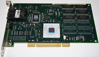 IBM Turboways ATM 155 PCI network interface card Why cells?
Consider a speech signal reduced to packets, and forced to share a link with bursty data traffic (traffic with some large data packets). No matter how small the speech packets could be made, they would always encounter full-size data packets, and under normal queuing conditions, might experience maximum queuing delays. That is why all packets, or "cells," should have the same small size. In addition the fixed cell structure means that ATM can be readily switched by hardware without the inherent delays introduced by software switched and routed frames.
Thus, the designers of ATM utilized small data cells to reduce jitter (delay variance, in this case) in the multiplexing of data streams. Reduction of jitter (and also end-to-end round-trip delays) is particularly important when carrying voice traffic, because the conversion of digitized voice into an analogue audio signal is an inherently real-time process, and to do a good job, the decoder (codec) that does this needs an evenly spaced (in time) stream of data items. If the next data item is not available when it is needed, the codec has no choice but to produce silence or guess — and if the data is late, it is useless, because the time period when it should have been converted to a signal has already passed.
At the time of the design of ATM, 155 Mbit/s Synchronous Digital Hierarchy (SDH) with 135 Mbit/s payload was considered a fast optical network link, and many Plesiochronous Digital Hierarchy (PDH) links in the digital network were considerably slower, ranging from 1.544 to 45 Mbit/s in the USA, and 2 to 34 Mbit/s in Europe.
At this rate, a typical full-length 1500 byte (12000-bit) data packet would take 77.42 µs to transmit. In a lower-speed link, such as a 1.544 Mbit/s T1 line, a 1500 byte packet would take up to 7.8 milliseconds.
A queuing delay induced by several such data packets might exceed the figure of 7.8 ms several times over, in addition to any packet generation delay in the shorter speech packet. This was clearly unacceptable for speech traffic, which needs to have low jitter in the data stream being fed into the codec if it is to produce good-quality sound. A packet voice system can produce this in a number of ways:
- Have a playback buffer between the network and the codec, one large enough to tide the codec over almost all the jitter in the data. This allows smoothing out the jitter, but the delay introduced by passage through the buffer would require echo cancellers even in local networks; this was considered too expensive at the time. Also, it would have increased the delay across the channel, and conversation is difficult over high-delay channels.
- Build a system which can inherently provide low jitter (and minimal overall delay) to traffic which needs it.
- Operate on a 1:1 user basis (i.e., a dedicated pipe).
The design of ATM aimed for a low-jitter network interface. However, to be able to provide short queuing delays, and for dategram's to be continued to be carried, the introduction of "cells" to the design became a requirement. ATM broke up all packets, data, and voice streams into 48-byte chunks, adding a 5-byte routing header to each one so that they could be reassembled later. The choice of 48 bytes was political rather than technical. When the CCITT (now ITU-T) was standardizing ATM, parties from the United States wanted a 64-byte payload because this was felt to be a good compromise in larger payloads optimized for data transmission and shorter payloads optimized for real-time applications like voice; parties from Europe wanted 32-byte payloads because the small size (and therefore short transmission times) simplify voice applications with respect to echo cancellation. Most of the European parties eventually came around to the arguments made by the Americans, but France and a few others held out for a shorter cell length. With 32 bytes, France would have been able to implement an ATM-based voice network with calls from one end of France to the other requiring no echo cancellation. 48 bytes (plus 5 header bytes = 53) was chosen as a compromise between the two sides. 5-byte headers were chosen because it was thought that 10% of the payload was the maximum price to pay for routing information. ATM multiplexed these 53-byte cells instead of packets. Doing so reduced the worst-case jitter due to cell contention by a factor of almost 30, reducing the need for echo cancellers.
Cells in practice
ATM supports different types of services via ATM adaptation layers (AAL). Standardized AALs include AAL1, AAL2, and AAL5, and the rarely usedTemplate:Citation needed AAL3 and AAL4. AAL1 is used for constant bit rate (CBR) services and circuit emulation. Synchronization is also maintained at AAL1. AAL2 through AAL4 are used for variable bit rate (VBR) services, and AAL5 for data. Which AAL is in use for a given cell is not encoded in the cell. Instead, it is negotiated by or configured at the endpoints on a per-virtual-connection basis.
Following the initial design of ATM, networks have become much faster. A 1500 byte (12000-bit) full-size Ethernet frame takes only 1.2 µs to transmit on a 10 Gbit/s network, reducing the need for small cells to reduce jitter due to contention. Some consider that this makes a case for replacing ATM with Ethernet in the network backbone. However, it should be noted that the increased link speeds by themselves do not alleviate jitter due to queuing. Additionally, the hardware for implementing the service adaptation for IP packets is expensive at very high speeds. Specifically, at speeds of OC-3 and above, the cost of segmentation and reassembly (SAR) hardware makes ATM less competitive for IP than Packet Over SONET (POS)Template:Citation needed; because of its fixed 48-byte cell payload, ATM is not suitable as a data link layer directly underlying IP (without the need for SAR at the data link level) since the OSI layer on which IP operates must provide an maximum transmission unit (|MTU) of at least 576 bytes. SAR performance limits mean that the fastest IP router ATM interfaces are STM16 - STM64 which actually compares, while Template:As of POS can operate at OC-192 (STM64) with higher speeds expected in the future.
On slower or congested links (622 Mbit/s and below), ATM does make sense, and for this reason most asymmetric digital subscriber line (ADSL) systems use ATM as an intermediate layer between the physical link layer and a Layer 2 protocol like PPP or Ethernet.Template:Citation needed
At these lower speeds, ATM provides a useful ability to carry multiple logical circuits on a single physical or virtual medium, although other techniques exist, such as Multi-link PPP and Ethernet VLANs, which are optional in VDSL implementations. DSL can be used as an access method for an ATM network, allowing a DSL termination point in a telephone central office to connect to many internet service providers across a wide-area ATM network. In the United States, at least, this has allowed DSL providers to provide DSL access to the customers of many internet service providers. Since one DSL termination point can support multiple ISPs, the economic feasibility of DSL is substantially improved.
Why virtual circuits?
ATM operates as a channel-based transport layer, using virtual circuits (VCs). This is encompassed in the concept of the Virtual Paths (VP) and Virtual Channels. Every ATM cell has an 8- or 12-bit Virtual Path Identifier (VPI) and 16-bit Virtual Channel Identifier (VCI) pair defined in its header. Together, these identify the virtual circuit used by the connection. The length of the VPI varies according to whether the cell is sent on the user-network interface (on the edge of the network), or if it is sent on the network-network interface (inside the network).
As these cells traverse an ATM network, switching takes place by changing the VPI/VCI values (label swapping). Although the VPI/VCI values are not necessarily consistent from one end of the connection to the other, the concept of a circuit is consistent (unlike IP, where any given packet could get to its destination by a different route than the others).
Another advantage of the use of virtual circuits comes with the ability to use them as a multiplexing layer, allowing different services (such as voice, Frame Relay, n* 64 channels, IP).
Using cells and virtual circuits for traffic engineering
Another key ATM concept involves the traffic contract. When an ATM circuit is set up each switch on the circuit is informed of the traffic class of the connection.
ATM traffic contracts form part of the mechanism by which "quality of service" (QoS) is ensured. There are four basic types (and several variants) which each have a set of parameters describing the connection.
- CBR - Constant bit rate: a Peak Cell Rate (PCR) is specified, which is constant.
- VBR - Variable bit rate: an average cell rate is specified, which can peak at a certain level for a maximum interval before being problematic.
- ABR - Available bit rate: a minimum guaranteed rate is specified.
- UBR - Unspecified bit rate: traffic is allocated to all remaining transmission capacity.
VBR has real-time and non-real-time variants, and serves for "bursty" traffic. Non-real-time is sometimes abbreviated to vbr-nrt.
Most traffic classes also introduce the concept of Cell Delay Variation Tolerance (CDVT), which defines the "clumping" of cells in time.
To maintain traffic contracts, networks usually use "shaping", a combination of queuing and marking of cells. "Traffic policing" generally enforces traffic contracts.
Traffic shaping
Traffic shaping usually takes place at the entry point to an ATM network and attempts to ensure that the cell flow will meet its traffic contract.
Traffic policing
To maintain network performance, networks may police virtual circuits against their traffic contracts. If a circuit is exceeding its traffic contract, the network can either drop the cells or mark the Cell Loss Priority (CLP) bit (to identify a cell as potentially redundant). Basic policing works on a cell by cell basis, but this is sub-optimal for encapsulated packet traffic (as discarding a single cell will invalidate the whole packet). As a result, schemes such as Partial Packet Discard (PPD) and Early Packet Discard (EPD) have been created that will discard a whole series of cells until the next frame starts. This reduces the number of useless cells in the network, saving bandwidth for full frames. EPD and PPD work with AAL5 connections as they use the frame end bit to detect the end of packets.
Types of virtual circuits and paths
ATM can build virtual circuits and virtual paths either statically or dynamically. Static circuits (permanent virtual circuits or PVCs) or paths (permanent virtual paths or PVPs) require that the circuit is provisioned as a series of segments, one for each pair of interfaces through which it passes.
PVPs and PVCs, though conceptually simple, require significant effort in large networks. They also do not support the re-routing of service in the event of a failure. Dynamically built PVPs (soft PVPs or SPVPs) and PVCs (soft PVCs or SPVCs), in contrast, are built by specifying the characteristics of the circuit (the service "contract") and the two end points.
Finally, ATM networks create and remove switched virtual circuits (SVCs) on demand when requested by an end piece of equipment. One application for SVCs is to carry individual telephone calls when a network of telephone switches are inter-connected using ATM. SVCs were also used in attempts to replace local area networks with ATM.
Virtual circuit routing
Most ATM networks supporting SPVPs, SPVCs, and SVCs use the Private Network Node Interface or Private Network-to-Network Interface (PNNI) protocol.
PNNI uses the same shortest-path-first algorithm used by OSPF and IS-IS to route IP packets to share topology information between switches and select a route through a network. PNNI also includes a very powerful summarization mechanism to allow construction of very large networks, as well as a call admission control (CAC) algorithm which determines the availability of sufficient bandwidth on a proposed route through a network in order to satisfy the service requirements of a VC or VP.
Call admission and connection establishment
A network must establish a connection before two parties can send cells to each other. In ATM this is called a virtual circuit (VC). It can be a permanent virtual circuit (PVC), which is created administratively on the end points, or a switched virtual circuit (SVC), which is created as needed by the communicating parties. SVC creation is managed by signaling, in which the requesting party indicates the address of the receiving party, the type of service requested, and whatever traffic parameters may be applicable to the selected service. "Call admission" is then performed by the network to confirm that the requested resources are available and that a route exists for the connection.
Reference model
ATM defines three layers:
- ATM Adaptation Layer (AAL) and
- ATM Layer correspond roughly to the OSI Data Link Layer
- Physical Layer, equivalent to OSI Physical Layer
Structure of an ATM cell
An ATM cell consists of a 5-byte header and a 48-byte payload. The payload size of 48 bytes was chosen as described above ("Why cells?").
ATM defines two different cell formats: UNI (User-Network Interface) and NNI (Network-Network Interface). Most ATM links use UNI cell format.
|
Diagram of the UNI ATM Cell
| 7
|
|
|
4
|
3
|
|
|
0
|
| GFC
|
VPI
|
VPI
|
VCI
|
VCI
|
| VCI
|
PT
|
CLP
|
| HEC
|
Payload and padding if necessary (48 bytes)
|
|
Diagram of the NNI ATM Cell
| 7
|
|
|
4
|
3
|
|
|
0
|
VPI
|
VPI
|
VCI
|
VCI
|
| VCI
|
PT
|
CLP
|
| HEC
|
Payload and padding if necessary (48 bytes)
|
|
- GFC = Generic Flow Control (4 bits) (default: 4-zero bits)
- VPI = Virtual Path Identifier (8 bits UNI) or (12 bits NNI)
- VCI = Virtual Channel identifier (16 bits)
- PT = Payload Type (3 bits)
- CLP = Cell Loss Priority (1-bit)
- HEC = Header Error Control (8-bit CRC, polynomial = X8 + X2 + X + 1)
ATM uses the PT field to designate various special kinds of cells for operations, administration and management (OAM) purposes, and to delineate packet boundaries in some AALs.
Several of ATM's link protocols use the HEC field to drive a CRC-based framing algorithm, which allows locating the ATM cells with no overhead required beyond what is otherwise needed for header protection. The 8-bit CRC is used to correct single-bit header errors and detect multi-bit header errors. When multi-bit header errors are detected, the current and subsequent cells are dropped until a cell with no header errors is found.
A UNI cell reserves the GFC field for a local flow control/submultiplexing system between users. This was intended to allow several terminals to share a single network connection, in the same way that two Integrated Services Digital Network (ISDN) phones can share a single basic rate ISDN connection. All four GFC bits must be zero by default.
The NNI cell format replicates the UNI format almost exactly, except that the 4-bit GFC field is re-allocated to the VPI field, extending the VPI to 12 bits. Thus, a single NNI ATM interconnection is capable of addressing almost 212 VPs of up to almost 216 VCs each
(in practice some of the VP and VC numbers are reserved).
Deployment
ATM became popular with telephone companies and many computer makers in the 1990s. However, even by the end of the decade, the better price/performance of Internet Protocol-based products was competing with ATM technology for integrating real-time and bursty network traffic.
Companies such as FORE Systems focussed on ATM products, while other large vendors such as Cisco Systems provided ATM as an option.
However, in 2005 the ATM Forum, which had been the trade organization promoting the technology, merged with groups promoting other technologies, and eventually became the Broadband Forum.
Notes
References
External links
FDDI
Abbreviation of Fiber Distributed Data Interface, a set of ANSI protocols for sending digital data over fiber optic cable. FDDI networks are token-passing networks, and support data rates of up to 100 Mbps (100 million bits) per second. FDDI networks are typically used as backbones for wide-area networks.
An extension to FDDI, called FDDI-2, supports the transmission of voice and video information as well as data. Another variation of FDDI, called FDDI Full Duplex Technology (FFDT) uses the same network infrastructure but can potentially support data rates up to 200 Mbps.
Fiber Distributed Data Interface (FDDI) provides a 100 Mbit/s optical standard for data transmission in a local area network that can extend in range up to Template:Convert. Although FDDI logical topology is a ring-based token network, it does not use the IEEE 802.5 token ring protocol as its basis; instead, its protocol is derived from the IEEE 802.4 token bus timed token protocol. In addition to covering large geographical areas, FDDI local area networks can support thousands of users. As a standard underlying medium it uses optical fiber, although it can use copper cable, in which case it may be referred to as CDDI (Copper Distributed Data Interface). FDDI offers both a Dual-Attached Station (DAS), counter-rotating token ring topology and a Single-Attached Station (SAS), token bus passing ring topology.
FDDI was considered an attractive campus backbone technology in the early to mid 1990s since existing Ethernet networks only offered 10 Mbit/s transfer speeds and Token Ring networks only offered 4 Mbit/s or 16 Mbit/s speeds. Thus it was the preferred choice of that era for a high-speed backbone, but FDDI has since been effectively obsolesced by fast Ethernet which offered the same 100 Mbit/s speeds, but at a much lower cost and, since 1998, by Gigabit Ethernet due to its speed, and even lower cost, and ubiquity.
FDDI, as a product of American National Standards Institute X3T9.5 (now X3T12), conforms to the Open Systems Interconnection (OSI) model of functional layering of LANs using other protocols. FDDI-II, a version of FDDI, adds the capability to add circuit-switched service to the network so that it can also handle voice and video signals. Work has started to connect FDDI networks to the developing Synchronous Optical Network SONET.
A FDDI network contains two rings, one as a secondary backup in case the primary ring fails. The primary ring offers up to 100 Mbit/s capacity. When a network has no requirement for the secondary ring to do backup, it can also carry data, extending capacity to 200 Mbit/s. The single ring can extend the maximum distance; a dual ring can extend Template:Convert. FDDI has a larger maximum-frame size (4,352 bytes) than standard 100 Mbit/s Ethernet which only supports a maximum-frame size of 1,500 bytes, allowing better throughput.
Designers normally construct FDDI rings in the form of a "dual ring of trees" (see network topology). A small number of devices (typically infrastructure devices such as routers and concentrators rather than host computers) connect to both rings - hence the term "dual-attached". Host computers then connect as single-attached devices to the routers or concentrators. The dual ring in its most degenerate form simply collapses into a single device. Typically, a computer-room contains the whole dual ring, although some implementations have deployed FDDI as a Metropolitan area network.
Mitigating failure
FDDI requires this network topology because the dual ring actually passes through each connected device and requires each such device to remain continuously operational.
The standard actually allows for optical bypasses, but network engineers consider these unreliable and error-prone. Devices such as workstations and minicomputers that might not come under the control of the network managers are not suitable for connection to the dual ring.
As an alternative to using a dual-attached connection, a workstation can obtain the same degree of resilience through a dual-homed connection made simultaneously to two separate devices in the same FDDI ring. One of the connections becomes active while the other one is automatically blocked. If the first connection fails, the backup link takes over with no perceptible delay.
Standards
FDDI standards include:
- ANSI X3.139-1987, Media Access Control (MAC) — also ISO 9314-2
- ANSI X3.148-1988, Physical Layer Protocol (PHY) — also ISO 9314-1
- ANSI X3.166-1989, Physical Medium Dependent (PMD) — also ISO 9314-3
- ANSI X3.184-1993, Single Mode Fiber Physical Medium Dependent (SMF-PMD) — also ISO 9314-4
- ANSI X3.229-1994, Station Management (SMT) — also ISO 9314-6
Welcome to the Course !
|


