Openphysics/DC circuits
Contents
Introduction to Direct Current (DC) Circuits
Electric Current
When a power source maintains a potential difference across a conductor, charges are allowed to continually move through it, thus producing a sustained electric field. This ordered motion of charge through a conductor is known as electric current.
An electric current only exists when there is a net movement of charge. Ordinarily, electrons withing a piece of metal wire would move rapidly and in random directions, but this merely constitutes a movement of charge, not a net movement. In order for there to be a net movement of charge, the motion must be ordered, not random, as occurs only when there is a potential difference between the two ends of the wire. Thus, electric current flows due to a difference in electrical potential. Stated another way, electric current is proportional to electrical potential.
As a result, electric current can be more concisely defined as the rate of flow of charge through a conductor:
I average= Qdelta / tdelta
Where I is the notation for electric current, Q is the magnitude of charge (in Coulombs), and t is the interval of time (in seconds).
Electric current is meansured in coulombs per second. One coulomb per second is known as an ampere (A) or "amp". The direction of current is determined by the direction that a postive charge would move along the conductor.
Drift Speed
Unlike electric current, drift speed is the speed at which a charged particle moves thrugh a wire. While the movement of charge associated with electric current apprears instantaneous, the measure of drift speed is much slower.
Practice Problems
1.) A service station charges a battery using a current of 5.5 A for 7.0 hours. How much charge passes through the battery?
Solution: By the equation for electric current, I = Qdelta/tdelta
7 hours x 60 min/hr x 60 s/min = 25200 s
I = 5.5 A, tdelta= 25200 s
Since I = Qdelta/tdelta, Qdelta= I tdelta
Qdelta = 25200 s (5.5 A)
Qdelta = 138,600 Coulombs
Resistance
Resistance is the opposition to current flow. As a result, electric current is proportional to one over resistance.
Conductors, which facilitate the movement of charge, have a low resistance, or allow current to flow fairly freely. Insulators, on the other hand, have a high resitance, thus opposing the movement of charge and restricting the flow of current.
For a video on electricity, current, and resistance, see khan academy:
Ohm's Law
R = V / I or V = I R
Where R is the notation for resistance, V is the potential difference across the object (in volts), and I is the electric current (in amps).
Resistance is measured in volts per amp. One volt per amp is known as an ohm (symbol: omega).
For a video featuring an in-depth explanation of Ohm's Law, as well as an application of Ohm's Law in several examples of circuits, see the following:
Series & Parallel Circuits & Ohm's Law Physics, part 4 - Eeris Fritz
Resistivity
In addition to its potential difference and electric current, an object's resistance is dependent on its shape and the type of material that it is made of. Each material has a different resistivity, or tendency toward resistance1. An object's resistance is thus dependent upon not only the specific material that it is made of, but also the way in which that material is shaped.
As a result, an object's resistance can also be found using its resistivity:
R = pl/A
Where R is object's resistance (in ohms), p is the resistivity of the material, l is the length of the material, and A is the object's crossectional area (l and A are commonly measured in meters).
1 http://www.thefreedictionary.com/resistivity
Practice Problems
1.) A wire of radius 1 mm and length 2 m is made of platinum (resistivity = 1 x 10⁻⁷). If a voltage of 9 V is applied between the ends of the wire, what will be the resulting current?
To solve this problem, use the equation for resistivity.
R = pl/A
Since the area of a circle is pi*r2, this equation can be rewritten as: R = pl/A
p = 1 x 10⁻⁷, l = 2 m, r = 0.001 m
R = (1 x 10⁻⁷)(2 m)/(pi*(0.001 m)2) = 0.064 ohms
Next, Ohm's Law must be applied.
If V = IR, then I = V/R
V = 9 V, R = 0.064 ohms
I = 9 V/0.064 ohms = 140 A
2.) An electric clothes dryer has a heating element with a resistance of 8.2 ohms.
a. What is the current in the element when it is connected to 200 V?
Solution: To solve this problem, Ohm's Law must be applied.
If V = IR, then I = V/R
V = 200 V, R = 8.2 ohms
I = 24.39 A
b. How much charge passes through the element in 50 min?
Solution: This part of the problem can be solved using the properties of current.
I = Qdelta/t
50 min x 60 seconds/1 min = 3000 seconds
24.39 A = Qdelta/3000 s
Qdelta = 73170.73 Coulombs
Electric Power
Electric power is the rate at which electrical energy is transformed. Within a substance such as a metal wire, electric energy is transformed into thermal energy through collisions between moving electrons and the atoms within the wire. In such collisions, the kinetic energy of the each of the electrons is transferred to the atoms with which they collide, increasing the kinetic energy of the atoms themselves. This increase in turn raises the overall temperature of the wire, resulting in an increased thermal energy that can then be transferred to another object.
Energy is transformed when a carrier of positive charge Q moves through a potential difference V, losing potential energy in the amount QV. Occuring over an interval of time t, power is equivalent to QV/t. Since current (I) is equal to Q/t, the equation for power can be written as:
P = IV
Where P is the notation for power, I is the electric current passing through the substance (in amps), and V is the potential difference across the substance (in volts).
Power is measured in watts (W), where one watt is equal to one Joule per second.
Using substitutions derived from Ohm's Law, the equation for power can also be written as:
P = I 2 R and P = V 2/ R
Electric Circuits
An electric circuit exists when both terminals (or both the positive and negatively charged ends) of a source of voltage, such as a battery, are connected by pathway that allows the flow of current.
An electric circuit is considered to be a DC circuit, or direct current circuit, if the current always moves in the same direction through this pathway.
Electromotive Force
Commonly known as an "emf", an electromotive force is the potential difference that drives the flow of charge from one end of such a pathway to the other and is produced by a source of voltage. Despite its misleading name, an electromotive force is the amount of work done per unit of charge; it is not in fact a force in the traditional sense. Rather, it is a voltage, and is thus measured in volts.
Terminal Voltage
Terminal voltage is another way of expressing a circuit's electromotive force. The terminal voltage of an electric circuit is the total voltage available to the circuit. This term is thus equivalent to a circuit's emf and can be found using the same equation:
V delta = E − I r
Where V is difference in voltage from the positive to the negative terminal of the voltage source, E is the circuit's emf or terminal voltage, I is the electric current, and r is the internal resistance of the voltage source.
For a video explaining the following:
Circuit Diagrams
Electric circuits contain three basic elements: batteries, resistors, and connecting wires. Using these components, the batteries represent the sources of voltage, the resistors are devices that control the flow of current (each with its own value of resistance), and the connecting wires provide the pathway that complete the circuit and allow current to flow.
Batteries are denoted by the symbol:
Where the longer line represents the positive (higher potential) terminal, and the shorter line represents the negative (lower potential) terminal.
Resistors are denoted by the symbol:
An example of a simple circuit diagram is as follows: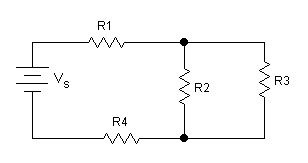
Where R1 and R4 are resistors in series, R2 and R3 are resistors in parallel, and Vs is the battery, or voltage source.
Types of Simple Circuits
There are two distinct ways of combing resistors within a circuit - in parallel and in series. These characteristics give rise to two types of simple circuits - parallel circuits and series circuits. More complex circuits consist of resistors both in parallel and in series, and thus operate based on a combination of the principles that follow.
Parallel Circuits
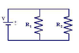
In a parallel circuit, resistors are placed side-by-side:
Equivalent Resistance
In order to calculate the total resistance of a parallel circuit, the circuit's equivalent resistance must be found. Equivalent resistance is the value of a single resistor that would replace all of the parallel resistors in a parallel circuit and draw the same amount of current. For more complex circuits that involve resistors in both parallel and series, this definition for equivalent resistance applies to the resistors in a parallel leg of a circuit. The reciprocal of the equivalent resistance is equal to the sum of the reciprocals of the individual resistances of each of the resistors in parallel:
1 / Rtotal = (1/R1) + (1/R2) + (1/R3) + ....(1/Rn)
Where Rtotal is the equivalent resistance of the parallel circuit (or of the parallel leg of a more complex circuit) and Rn is the individual resistance of a parallel resistor in the circuit.
Series Circuits
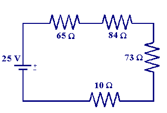
In a series circuit, resistors are placed one after the other:
Calculating Resistance
In a series circuit, the total resistance of the circuit is calculated simply by adding up the resistances of each individual resistor in the circuit:
Rtotal = R1+R2+R3+....Rn
Where Rtotal is the total resistance of the circuit and Rn is the resistance of an individual resistor in the circuit.
For a video walk-through of series circuits:
Circuits Part 2 Circuits Part 2
Practice Problems
1.) a. Determine the equivalent resistance of the circuit shown below if R1 = 850 ohms, R2 = 650 ohms, and R3 = 470 ohms.
Solution: Since resistors 1 and 2 are arranged in parallel in the circuit, their equivalent resistance can be found.
1/Requivalent = 1/R1 + 1/R2
1/Requivalent = 1/850 + 1/650
1/Requivalent = 368.33 ohms
Since resistor 3 would be arranged in series with the combined resistor representing resistors 1 and 2, the total resistance of the circuit can be found by adding the equivalent resistance previous calculated to the resistance of the third resistor.
Rtotal = Req + R3
Rtotal = 368.33 + 470
Rtotal= 838.33 ohms
b. Determine the voltage across each resistor.
Solution: Since the resistors are arranged in parallel, the voltage is the same through all of the resistors.
VR1 = VR2 = VR3
By Ohm's Law, V = IR
Thus, in order to solve for the voltage through each of the resistors, the current through each resistor must be found.
This equation can be rewritten as I = V/R to solve for the current through the resistors.
Vs = 12 V, R = 838.33 ohms
I = 12/838.33
I = 0.0143 A
Once the current has been found, it can be plugged back into the original equation for Ohm's Law to solve for the voltage.
Using the resistance of R3, the voltage leaving the resistor can be determined.
I = 0.0143 A, R = 470 ohms
VR3 = (0.0143)*470
VR3 = 6.728 V
However, this value is the voltage leaving the resistor, rather than the voltage through each resistor.
To find the voltage through each resistor, this calculated value must be substracted from the voltage of the source, which feeds into each of the resistors.
V = Vs - VR3
V = 12 - 6.728
V = 5.272 V
2.) a. What is the internal resistance of a 12 V car battery whose terminal voltage drops to 8.2 V when the starter draws 46 A?
Solution: To start this problem, the given variables should first be defined.
Vsource = 12 V, Vstarter = voltage drop of the starter = 8.2 V, I = 46 A
Once the information has been stated, the voltage drop of the battery must be found.
VB = Vsource - Vstarter
VB = 12 - 8.2
VB = 3.8 V
Now that the voltage of the battery has been determined, the internal resistance of the battery can be found using Ohm's Law.
RB = VB/I
RB = 3.8/46
RB = 0.083 ohms
b. What is the internal resistance of the starter?
We can solve for this value using Ohm's Law and the information given and previously determined.
Rstarter = Vstarter/I
Rstarter = 8.2 V, I = 46 A
Rstarter = 8.2/46
Rstarter = 0.178 ohms
For a video walk-through of another circuit problem, see khan academy:
Capacitance
Capacitance is the ability to store charge. An object's capacitance is a function of both charge and voltage, and can be determined using the following equation:
Q = CV or C = Q / V
Where Q is the charge in coulombs, V is the voltage in volts, and C is the capacitance, measured in farads.
Consequently, a capacitor is a device that stores charge. Just as resistors can be arranged in parallel and in series, capacitors can be arranged in these two configurations as well.
For a video explaining capacitance, see khan academy:
Capacitors in Parallel
Capacitators in parallel are configured as follows:
For capacitors arranged in parallel, the circuit's capacitance can be found simply by taking the sum of the capactances of each individual capacitor.
Ctotal = C1 + C2 + C3 +...Cn
Where Ctotal is the total capacitance of the capacitors in parallel and Cn is the capacitance of an individual capacitor in the circuit.
Capacitors in Series
Capacitors in series are configured as follows:
To find the total capacitance of multiple capacitors arranged in series, their equivalent capacitance must be found. Treating them in the same way as resistors in parallel, the reciprocal of the total capacitance is equal to the sum of the reciprocals of the individual capacitances of each of the capacitors in series:
1/Ctotal = (1/C1) + (1/C2) + (1/C3) +...(1/Cn)
Practice Problems
1.) The charge on a capacitor increases by 21 µC when the voltage across it increases from 80 V to 121 V. What is the capacitance of the capacitor?
Solution: To solve this problem, it must first be recognized that the problem deals with two separare values of charge. Thus, two equations can be set up using the equation for capacitance.
Q1 = CV1 Q2 = CV2
From these equations, we can set up the following statement of equality:
Q2 - Q1 = CV2 - CV1
By simplifying this new equation, the capacitance of the the capacitor can be solved for.
Q2 - Q1= C(V2 - V1)
C = (Q2 - Q1) / (V2 - V1)
From the original problem, it is given that Q2 - Q1 = 21 µC = 21 x 10-6 C
From the original problem, V2 = 121 V and V1 = 80 V.
V2 - V1 = 121 V - 80 V = 41 V
Thus, if C = (Q2 - Q1) / (V2 - V1):
C = 21 x 10-6/41
C = 5.12 x 10⁻⁷ F
2.) Given only one 15 F and one 85 F capacitor, list all of the possible values of capacitance that can be obtained.
Solution: There are four ways in which the two capacitors mentioned could be arranged within a circuit: in parallel, in series, with only the first capacitor, and with only the second capacitor.
If the two capacitors are arranged in parallel, the circuit's capacitance can be determined simply by adding up their individual capacitances.
Ctotal = C1 + C2, where C1 = 15 F and C2 = 85 F
Ctotal = 15 + 85
Ctotal = 100 F
If the two capacitors are arranged in series, the circuit's capacitance can be found by finding the sum of the reciprocals of each of the individual capacitances.
1/Ctotal = 1/C1 + 1/C2
1/Ctotal = 1/15 + 1/85
1/Ctotal = 0.078
Ctotal = 12.75 F
If only one of the two capacitors is included in the circuit, the total capacitance would be equal to the individual capacitance of either the first or the second capacitor.
Ctotal = C1 = 15 F
OR:
Ctotal = C2 = 85 F
Kirchhoff's Laws
In more complex circuits, resistors cannot be classified as merely parallel or series. Instead, we must analyze them according to two rules determined by Gustav Kirchhoff, commonly known as "Kirchhoff's Laws."
The Junction Rule
Also referred to as "Kirchhoff's Current Law" and the "Node Rule," the Junction Rule states that at any junction point (a point where a circuit's path splits into multiple paths) within a circuit, the sum of the currents entering the junction must equal the sum of the currents exiting the junction. In other words:
Itotal = I1 + I2 +...I3
Where Itotal is the total current entering the junction, and In is the value of one of the currents leaving the junction, or vice versa.
Thus, the Junction Rule is essentially a statement of the Law of Conservation of Charge.
The Loop Rule
Also referred to as "Kirchhoff's Voltage Law," the Loop Rule states that the sum of the changes in electric potential, or voltage, around any closed path (or "loop") of a circuit must equal zero. In other words:
0 = VS − VR1 − VR2 − ...VRn or VS = VR1 + VR2 +...VRn
Where VS is the voltage of the voltage source, or battery, and VRn is the voltage at each resistor in loop of the circuit that is being analyzed.
Thus, the Loop Rule states that all decreases in electrical potential energy (caused by resistors in the direction of current) must equal all increases in electrical potential energy (caused by a voltage source, such as a battery). Therefore, if the path of a circuit is followed starting at any one point along the circuit, the voltage at this starting point must be the same as the voltage that is arrived at when the circuit is traced back to this point.
As a result, the Loop Rule is essentially a statement of the Law of Conservation of Energy.
Problem Solving with Kirchhoff's Laws
When analyzing complex circuits in order to solve for resistance, voltage, and current, the equations previously detailed must be utilized in conjunction with Kirchhoff's Laws. The following process combines these principles to allow for the analysis of such circuits and the determination of unknown variables.
Problem Solving Steps:
1. Label the current: Identify the current between two junction points and choose the direction of the current, marking it with an arrow.
2. Identify the unknown variables: For each unknown variable, set up an independent equation.
3. Apply Kirchhoff's Junction Rule at 1 or more junction points.
4. Apply Kirchhoff's Loop Rule to one or more loop IN ONE DIRECTION.
5. Solve the equations.
Determining Whether Values are (+) or (-)
For a resistor, use Ohm's Law to determine the direction. If the direction of the current and the loop are the same, then the value is negative. If the direction of the loop is different than the direction of the current, the value is positive.
For a battery or voltage source, the value is positive if the direction of the loop is from the positive terminal to the negative terminal of the battery.If it is in the opposite direction, the value is negative.
Important Points to Remember
1. When going across a resistor in the same direction as the current, the potential drops by IR.
2. When going across a resistor in the opposite direction as the current, the potential increases by IR.
3. When going from the negative to positive terminal of a source of emf (a voltage source), the potential increases by V.
4. When going from the positive to the negative terminal of a source of emf, the potential decreases by V.
Practice Problems
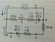
1.) Calculate the currents I1, I2, and I3 in the three branches of the circuit.
Solution:To solve this complex circuit, Kirchhoff's Laws must be applied. The problem can be solved according to the series of problem solving steps listed above.
1. Since the currents and directions are labeled in the diagram, this step has already been done.
2. There are three unknowns in the problem: I1, I2, and I3. Therefore, three equations will be needed to solve for these variables.
3. Kirchhoff's junction rule can be applied at point a, where I3 enters and I2 and I1 leave the junction. Thus:
I3 = I1 + I2 [Equation a]
4. Kirchhoff's loop rule can be applied to two diff erent closed loops within the circuit. Starting with the upper loop (loop ahdcba), there is a potential decrease from a to h (Vha = - (I1)(30 ohms)), no change from h to d, a potential increase of 45 V from d to c (Vcd = +45 V), and a potential decrease from c to a through the two resistors (by an amount Vac = - (I3)(40 ohms + 1 ohm) = - (41 ohms)(I3)
Thus, the following equation can be formed:
Vha + Vcd + Vac = 0
This can be rewritten as:
- 30 I1 + 45 - 41 I3 = 0 [Equation b]
For the lower loop (loop abcdefga):
Vha = - (I1)(30 ohms)
Vdh = 0
Ved = I2(20 ohms)
Vfe = I2(1 ohm),
Vgf = - 80 V,
Vag = 0
Thus, the sum of the potential changes around this loop can be represented by the equation:
- 30 I1 + (20+1)I2 - 80 = 0 [Equation c]
5. Now that three equations have been established - one for each unknown variable - all that remains in order to solve the problem is to solve each of the equations for these variables.
From Equation c, the variable I2 can be isolated:
I2 = (80+30 I1)/21
I2 = 3.8 + 1.4 I1 [Equation d]
From Equation b, the variable I3 can be isolated.
I3 = (45-30 I1)/41
I3 = 1.1 - 0.73 I1 [Equation e]
Equations d and e can now be substituted into Equation a to solve for the variable I1.
From Equation a (rewritten):
I1 = I3 - I2
I1 = (1.1 - 0.73 I1) - (3.8 + 1.4 I1)
By combining like terms:
3.1 I1 = - 2.7
I1 = - 0.87 A
The negative sign indicates that the direction of I1 assumed in the diagram is opposite to the actual direction in which I1 flows through the circuit.
This value of I1 can then be plugged back into Equations d and e to solve for I2 and I3.
Equation d:
I2 = 3.8 + 1.4 I1
I2 = 3.8 + 1.4 (-0.87)
I2 = 2.6 A
Equation e:
I3 = 1.1 - 0.73 I1
I3 = 1.1 - 0.73 (-0.87)
I3 = 1.7 A
Thus, I1 = - 0.87 A, I2 = 2.6 A, and I3 = 1.7 A.
Meters
Meters are devices that, when inserted into circuits, can be used to take accurate measurements of properties such as voltage, resistance, and current. The three meters most commonly used in direct current circuits are the ohmmeter, voltmeter, and ammeter.
Ohmmeter
Used to measure the resistance of a circuit, ohmmeters apply an electric potential across a component of the circuit and measure the current at that point. From these values of voltage (electric potential) and current, the circuit's resistance can then be accurately determined through a simple calculation involving Ohm's Law. Unlike the other two common types of meters, ohmmeters are not used in live circuits.
Ohmmeters are typically denoted as follows:
Voltmeter
Used to measure the voltage or electric potential across a component of a circuit, voltmeters are wired in parallel within live circuits and possess a very high internal resistance, thus minimizing the current drawn by the meter and providing a more accurate measure of voltage.
Voltmeters are typically denoted as follows:
Ammeter
Used to measure the current in a circuit, ammeters are wired in series within live circuits and possess a very small internal resistance, thus minimizing their impact on the circuit and providing an accurate measure of the circuit's current.
Ammeters are typically denoted as follows:
Works Cited
Leduc, Steven A., and John Miller. "Direct Current Circuits." Cracking the AP Physics B Exam. New York: Random House, 2011. 223-46. Print.
Leduc, Steven A., and John Miller. "Electric Potential and Capacitance." Cracking the AP Physics B Exam. New York: Random House, 2011. 203-22. Print.
Giancoli, Douglas C. "DC Circuits." Physics: Principles with Applications. Upper Saddle River, N.J: Pearson, 2005. 520-53. Print.
Giancoli, Douglas C. "Electric Currents." Physics: Principles with Applications. Upper Saddle River, N.J: Pearson, 2005. 493-519. Print.

