Come fly with me/Grades 7,8,9/PHYSICAL SCIENCE - Activities 1 - 23
- David C. Housel and Doreen K.M. Housel, 1983.
- Reproduced with permission
"It's just a matter of imagination how far we go with rockets. You haven't seen anything yet." ..Robert Goddard 1945
PHYSICAL SCIENCE OBJECTIVES
- to gain a working knowledge of the principles of flight.
- to understand that flight is possible only within bounds of certain scientific principles.
- to understand the forces that act on an aircraft.
- to understand the basic principles of propulsion.
Contents
- 1 1. WHY AN AIRPLANE FLIES
- 2 2. AIRPLANE CONTROL SURFACES
- 3 3. WIND TUNNEL
- 4 4. PROPELLER THRUST DEMO
- 5 5. FLIGHT INSTRUMENTS
- 6 6. BUILDING A MODEL AIRPLANE
- 7 7. ELECTRICAL CIRCUITRY / AIRCRAFT LIGHTS
- 8 8. AIRPORT FIELD TRIP
- 9 9. BUILDING A MODEL ROCKET
- 10 10. ROCKET NOZZLES
- 11 11. EASY AS 1-2-3
- 12 12. CONSTRUCTING A "THRUSTOMETER"
- 13 13. RECOVERING SPACECRAFT WITH PARACHUTES
- 14 14. RECOVERING SPACECRAFT WITH PARAGLIDERS
- 15 15. WIRING A LAUNCH SYSTEM
- 16 16. MODEL ROCKET CONTEST
- 17 17. BE COOL
- 18 18. SATELLITES IN ORBIT
- 19 19. OVAL ORBITS
- 20 20. INERTIA & GRAVITY - CIRCULAR ORBITS
- 21 21. "G" WIZZ
- 22 22. NAVIGATING IN SPACE
- 23 23. ROVE, ROVE, ROVE THE MOON...
1. WHY AN AIRPLANE FLIES
SUBJECT:
Science
GRADE:
7,8,9
GROUP SIZE:
Large Group
TIME:
45 minutes
TYPE OF ACTIVITY:
Student Activity and Demonstration
TEACHING STRATEGY:
Expository Guided Discovery
CONCEPTS:
Lift, Thrust, Drag, Bernoulli‘s principle
SKILLS:
Observation Inference, Modeling
Objectives: To review the concepts of Lift, Thrust, Drag, and Gravity in relationship to flight; to review and demonstrate Bernoulli‘s Principle.
Materials: Paper; pencils; study sheet.
Teacher Background Information: Many ways are available to demonstrate Bernoulli's principle simply in the classroom. Several ways are given here. Additional information on flight is available in the K - 6 edition of Come Fly with Me!.
Procedure:
A.
- Have the students tape a piece of paper to the side of a pencil.
- Hold the pencil sideways in two hands and,
- Blow gently across the top of the paper.
- Observe the action of the paper.
B.
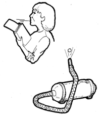
- Place the edge of a piece of paper between the pages of a book.
- Hold the book at an angle and,
- blow gently across the edge of the book with the paper in it.
- Observe the paper.
C.
- Attach the hose of a vacuum cleaner to the "blow" connection.
- Hold the hose straight up and turn the vacuum on.
- Place a ping pong ball in the stream of air blowing out of the hose.
- Observe the action of the ball.
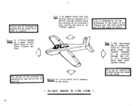
Note: In all cases the paper should rise and the ball should "fly" in the stream of air. The movement of air over the curved surface of the paper (airfoil) creates a low pressure area above the "wing" and allows the higher pressure air below the paper to "lift" it. Bernoulli‘s principle states that a fluid-like air exerts less pressure when it is moving quickly than when it is moving slowly. (Actually, an increase in the velocity of a fluid is always accompanied by a decrease in the pressure exerted by that fluid.) The lift created by the movement of air over a wing must be enough to support the weight of a plane and its contents for the plane to fly.
Another force acting against a plane is drag. Drag is created by the resistance of the air to the movement of a plane through the air and the mass of the plane. Usually, the sleeker the design, the less drag is created. The action used to counteract drag is forward motion. This motion is created by the "thrust" of a motor or engine in a powered plane or by gravity in a glider.
- Have the students review the diagram on the next page.
- Have them identify how each of the forces affecting flight are present in their plane.
Extensions:
Have the students research Bernoulli and learn more about the experiments he did which led to the description of the principle bearing his name. Have the students consider how Bernoulli's principle works in a rocket with no wings. Have the students explore ways to increase lift in a wing.Explore the effects of different shapes in wings on lift.
2. AIRPLANE CONTROL SURFACES
SUBJECT:
Science
GRADE:
7,8,9
GROUP SIZE:
Small or Large
TIME:
2-45 Minute periods
TYPE OF ACTIVITY:
Student Investigation and Teacher Discussion
TEACHING STRATEGY:
Expository Guided Discovery
CONCEPTS:
Roll, Pitch, Yaw, Control Surface
SKILLS:
Modeling, Manipulation of Variables
Objectives: To learn the names of the control surfaces of an airplane; to discover the effects of the manipulation of control surfaces on the flight characteristics of an airplane; to review the four forces of flight and relate the manipulation of the control surfaces to the four forces.
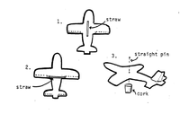
Materials: Three 20cm x 20cm pieces of light cardboard cut into airplane shapes (use the pattern provided); two pieces of soda straw about 7cm long; 1 pencil with an eraser or a cork; 1 straight pin; tape.
Procedure:
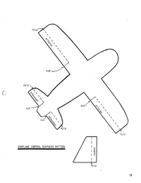
- Cut out three airplane shapes from the cardboard using the pattern provided.
- Save scrap pieces and cut out three tail pieces also shown in the pattern.
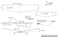
- Cut the solid lines indicated for plane 1 which will produce ailerons. Fold on the dotted lines. Tape or glue a soda straw piece on the bottom of the airplane as shown in the diagram. Attach one of the tail pieces.
- Assemble plane 2 as shown, cutting the lines which produce elevators. Attach the second piece of straw on the bottom of the plane's wing crossing the center of balance. Attach a tail piece.
- Assemble plane 3 producing a tail which has a moveable rudder as shown. Attach this plane to the eraser of the pencil or to a cork as in the diagram.
- Place a knitting needle or piece of wire through the straws of the first two planes and gently blow or hold them in front of a fan. Bend one aileron up and one down.
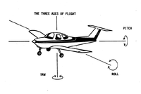
Have the students observe the resulting action on the plane. Reverse the aileron positions and observe again. with the second plane, raise or lower the elevator and observe the action. With the third plane, move the rudder left or right and hold in front of the air source again. Review with the students that the ailerons act on the axis of ROLL, the elevators act on the axis of PITCH and the rudder acts on the axis of YAW.
Teacher Note:
It is important that the students understand that the rudder on a plane in flight does not turn a plane like the rudder of a boat. In a plane the rudder acts on the axis of yaw. Turning is accomplished by banking the plane with the ailerons and the action of the rudder combined. The rudder does keep the plane straight or can be used to offset side forces from the wind in order to maintain a particular path over the ground. It should become apparent to the students that the control surfaces are used to put the plane into a particular attitude relative to the ground (straight and level). This attitude then allows the pilot to cause the plane to climb or descend, to turn right or left, to correct a flight path over the ground, or to do a combination of any of these things.
Extensions: You may wish to have the students do an online search for video clips of early attempts at aircraft design which failed.
3. WIND TUNNEL
SUBJECT:
Science
GRADE:
7,8,9
GROUP SIZE:
Small
TIME:
2 or 3 60 minute periods
TYPE OF ACTIVITY:
Construction and Student Investigation
TEACHING STRATEGY:
Expository Guided Discovery
CONCEPTS:
Scale Model Control Surface
SKILLS:
Modeling, Experimenting Interpreting Data
Objectives: To demonstrate the effects of the manipulation of flight control surfaces of a plane on its flight characteristics; to demonstrate on a small scale how scientists test those characteristics on larger planes and rockets before they fly; to realize some of the benefits which may occur from scientific “modeling".
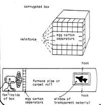
Materials: Piece of furnace pipe or carpet roll about 1.3 meters long; piece of transparency film for the tunnel window; separations from an egg carton (available at the grocery, some bakeries, a restaurant, or you may build a similar one from strips of light cardboard); heavy cardboard or a box the same size as the egg carton divider; book tape or duct tape; an electric fan; 2 small hooks of the type used to hang cups; metal shears or a saber saw depending on the material your tunnel is to be constructed of.
Teacher Background Information:
The tunnel~like chambers through which air is passed at different velocities are used to study airflow over an object like a plane or rocket. The automobile industry also uses wind tunnels in their research to produce more fuel efficient cars. Some of the wind tunnels in the United States are large enough to hold full size planes or rockets for testing. One such tunnel is at the Langley, NASA Research facility in Virginia. A supersonic tunnel is at the NASA Lewis Research Center in Cleveland, Ohio. A model of the shuttle was tested and perfected in this tunnel before it was produced.
There are any number of small wind tunnels which you or a small group of students can prepare. The one suggested here is a relatively simple one requiring a minimum of exotic materials. If you would like to prepare a more sophisticated model, refer to additional sources such as science teacher resource manuals or online resources.
Procedure:
Open the carton separators and strengthen the corners with tape. Open a box at both ends and place the separator grid into the box. They should fit snugly. Cut a window near one end of the roll or pipe and cover it with the clear film or acetate. Tape the film down using the book binder's tape. Fasten the hooks on opposite sides of the tube so that a plane hanging from the top one will be positioned in front of the window. (Refer to the illustration). Set the egg carton separations flush against the pipe or tube and place a fan in the box holding the separators. The separators will straighten the swirling air from the fan.
1. Have the students prepare a suspension system for the model airplane to be tested.
- a. Use a strong rubber band of the type you find on Civil Air Patrol, FAA model airplanes reprint GA-20-30. Cut the band in one place.
- b. String two note book paper reinforcement rings on the rubber band and glue them together.
- c. Tie the cut ends of the rubber band back together again
- d. To attach the model to be tested, place a pin through the model and the ring near the center of gravity of the model.
- e. Attach a similar rubber band to the lower hook as well.
2. Have the students start by building paper airplane models and testing the effects of manipulation of the control surfaces of the model. They should discover that to climb, elevators are up; to dive, elevators are down; to turn right, the rudder is right, the right aileron is up, the left aileron is down; to turn left, the rudder is left, the left aileron is up, the right aileron is down.
3. Have the students investigate the effects of changing the center of gravity on the stability of the plane.
Extensions: Have the students prepare and test model rockets, before actual flight, in the tunnel and compare the actual flight results with their data collected from the tests after launch. Have them find out more about wind tunnel testing of automobiles and investigate spin offs from the science of aerodynamics to the auto industry.
4. PROPELLER THRUST DEMO
SUBJECT:
Science
GRADE:
7,8,9
GROUP SIZE:
Large
TIME:
45 minutes
TYPE OF ACTIVITY:
Teacher Demonstration Student Investigation
TEACHING STRATEGY:
Guided Discovery
CONCEPTS:
Propeller Pitch, Newton's 3rd Law, Thrust
SKILLS:
Observation, Inference, Hypothesizing
Objectives: To investigate how a propeller produces thrust and the results of that thrust; to relate the results of this investigation to Newton's Third Law of Motion.
Materials: 6 or more round pencils or pieces of doweling; a flat board; an electric fan and extension cord; model airplane propellers.
SAFETY NOTE: DO NOT ALLOW THE STUDENTS TO INVESTIGATE THE PITCH OF THE PROPELLER WHILE THE FAN IS PLUGGED IN!
Procedure:
- Have the students examine the propellers and the blades of the fan. Have them hypothesize as to the direction of thrust based on the direction of rotation.
- Have them rotate the blades slowly to see what action they may have on the air.
- Place the board on several pencils which have been placed parallel to one another on a hard flat surface. Place the fan on the board and plug it in.
- Have the students observe the resulting action/ reaction and feel the thrust of air from the propeller in the fan.
- Have them then apply this information to their hypotheses and explain which direction thrust will be produced by the model airplane propellers.
Extension: Have the students actually make a propeller out of wood. Have them investigate the effect of pitch (angle of attack) of different propellers. Relate this experiment to the one on rocket nozzles which dealt with velocity as a result of pressure. Relate the propeller concept to a boomerang.
5. FLIGHT INSTRUMENTS
SUBJECT:
Science
GRADE:
7,8,9
GROUP SIZE:
Individual or Small group
TIME:
2-45 Minute periods
TYPE OF ACTIVITY:
Simulation Student Investigation
TEACHING STRATEGY:
Expository Guided Discovery
CONCEPTS:
Flight Instruments Visual Flight Rules Instrument Flight Rules
SKILLS:
Construction, Observation Interpreting Data
Objectives: To introduce the basic flight instruments contained in an airplane; to manipulate models of flight instruments and learn how to read them.
Materials: Activity sheets; copies of the demonstration sheets for each student or group of students; tag board; scissors; rubber cement; brass fasteners.
Teacher Background Information:
This lesson deals with the instruments used in beginning flight training. At first glance, the instruments look difficult to use but, in fact, with a minimum of practice they are quite simple. The lesson, though it takes time to prepare, is well worth the effort as a model for reading data from instruments and as an an example of the importance of precision when reading instruments. Early navigation in planes meant following landmarks on the ground by day and by night, following a trail of bonfires set by farmers. Later, light beacons spaced a few miles apart, were the state-of-the-art for night flying in good weather. Sometimes pilots were forced to land in a farmer's field along the way if weather turned bad and the farmer would find passengers from the airline as uninvited guests for the night. By the late 1920's and early '30's, a system of emergency airports had also been established along cross continent routes. Modern systems of navigation use radio beacons which are read by instruments in the plane and point the way along a flight path.
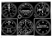
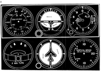
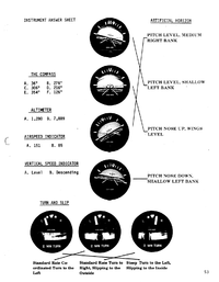
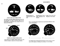
The AIRSPEED INDICATOR is read like the speedometer of a car and tells the pilot how fast the plane is moving through the air. The speed of a head wind would be subtracted from the airspeed reading to arrive at the speed over the ground (ground speed). Tail winds should be added to the airspeed. Colored arcs on each plane's airspeed indicator tell the pilot what the safe operating speeds are and when flaps or landing gear can be extended.
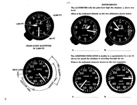
The ALTIMETER tells the pilot how high above sea level the plane is which can be interpreted as how high above the ground the plane is by looking at a map and finding the altitude of the ground below. There are 3 hands on the altimeter. The shortest indicates 10,000 feet, the middle length indicates 1,000 feet and the longest hand indicates 100 foot increments.
The TURN AND SLIP INDICATOR tells the pilot when he or she is making a coordinated turn. The needle indicates how the ailerons are being used and the ball indicates whether the rudder is being used correctly to balance the turn. The ball stays in the center when a turn is balanced, otherwise the ball "slips" to the side.
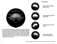
The ARTIFICIAL HORIZON indicates at what angle the plane is climbing, descending or banking. This instrument is essential when a pilot can not see outside.
The VERTICAL SPEED INDICATOR tells the pilot how fast the plane is climbing or descending in feet per minute.
The COMPASS indicates magnetic heading.
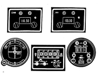
Several other instruments are included in the handouts. Have the students do a little research to find out how they work and what they are used for.
Procedure:
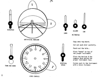
- Have the students carefully cut out the instrument faces from the sheets.
- Glue the faces on tagboard.
- Cut out the hands or dials which move and ..
- Attach them to the instrument faces with brass fasteners.
- Review with the students how to read the instruments using the activity sheets.
- Have the students set the dials on the instruments they made to read at the same values as the instruments on the activity sheet.
- Show the students some examples of different settings on a demonstration instrument and ask them to interpret what the setting or the reading means.
- Prepare a list of possible instrument readings and have the students set their instruments to match the readings. Have the students check each other.
- Have them identify which instruments are needed for flying VFR (on visual flight rules).
- Have them identify the additional instruments needed for IFR flying (instrument flight rules) in bad weather or through clouds.
Extensions:
Have the students prepare a mock-up of a plane's control panel complete with radios. Have them research and add to the panel, instruments which are found on more expensive planes, then, explain their function to the class. Take a trip to a local airport and see the actual instruments in a plane. Have a pilot or air traffic controller come to the class and talk about the instruments and flying. Arrange for a flight to see the instruments and controls in use. (See activity # 8).
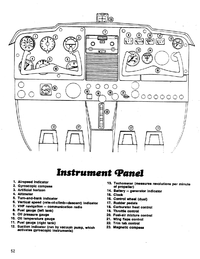
Instrument Panel
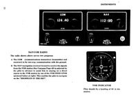
Airspeed indicator. Gyroscopic compass. Artificial horizon. Altimeter Turn-and-bank indicator. Vertical speed (rate-of-climb and descent) indicator. VHF navigation - communication radio. Fuel gauge (left tank) Oil pressure gauge. Oil temperature gauge. Fuel gauge (right tank). Suction indicator (run by vacuum pump, which activates gyroscopic instruments). Tachometer (measures revolutions per minute of propeller). Battery - generator indicator. Clock. Control wheel (dual). Rudder pedals. Carburetor heat control. Throttle control. Fuel-air mixture control. Wing flaps control. Trim tab control. Magnetic compass.
INSTRUMENT ANSWER SHEET
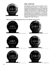
THE COMPASS
The magnetic compass is used in airplanes is a simple self contained instrument. A "compass card” is mounted on a floating ring which has two magnetized needles, which always point to magnetic north. The compass card has letters for cardinal headings, that is, N (north), E (east), S (south) and W (west). Each 30° interval of direction is represented by a number from which the last zero is omitted. Between the numbers, the card is graduated for each 5°. For example, on the compass 240° would look like 24.
INDICATED ALTITUDE
The AIRSPEED INDICATOR is similar to a speedometer in a car. It shows the speed the airplane is traveling through the air.
6. BUILDING A MODEL AIRPLANE
SUBJECT:
Science
GRADE:
7,8,9
GROUP SIZE:
Individual or Small
TIME:
Several 45 minute periods
TYPE OF ACTIVITY:
Construction and Testing of models
TEACHING STRATEGY:
Expository Guided Discovery
CONCEPTS:
Forces of Flight Stability
SKILLS:
Construction Modeling Manipulation and Control of Variables
Objectives: To review the parts of an airplane; to produce, test, and fly a model airplane; to review the effect of forces which influence flight.
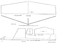
Materials: Model airplane kits or balsa sheets and sticks (as called for in the model for which plans are provided at the back of this lesson). For other models, check online at estesrockets.com.
Procedure:
1. Have the students assemble their planes according to the directions.
2. Test fly the planes and balance them to achieve the most stable flight characteristics.
3. Have the students try to identify the possible causes of any problems with the flight of their plane. what forces might be out of balance? what control surfaces on a plane might counteract the problem? Where is the center of balance in the plane?
4. If the students are not familiar with the control surfaces and their effect on flight, review each of the axes of flight and the parts of the plane which control those axes. (See the study sheet in lesson # 2.)
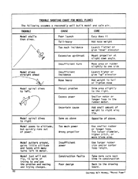
5. If the students still cannot identify the cause of the problem, refer to the trouble shooting sheet.
Extensions: Have a flying contest with the planes. Give points for the longest flight; the highest; the furthest;
the most acrobatic; the best design; best built. Have the class work together to build a more complex model, perhaps one with an engine. Have a local enthusiast bring a radio controlled plane or a control line model and fly it for the class. Take a field trip to a local airport and have a pilot show the students the control surfaces and the airplane controls which move them on a full size plane.
Courtesy of Walt Mooney, "Peanut Power"
7. ELECTRICAL CIRCUITRY / AIRCRAFT LIGHTS
SUBJECT:
Science
GRADE:
7,8,9
GROUP SIZE:
Individual or Small Group
TIME:
Several 45 minute periods
TYPE OF ACTIVITY:
Student Investigation
TEACHING STRATEGY:
Guided Discovery
CONCEPTS:
Parallel Circuit Series Circuit Circuit Breaker
SKILLS:
Construction Modeling Interpreting Data Reading Diagrams
Objectives: To have the students apply principles of circuitry to the wiring of a model aircraft; to become familiar with the clearance light lighting patterns used on aircraft and their meaning.
Materials: Model plane (preferably built by the student); Several feet of light wire (18 gage or less); small flashlight bulbs (at least three per plane though some students may use as many as 7); thin paint in red and green; toggle switches (optional); 2 - 1 1/2 volt dry cells per student; aircraft lighting specs (available from aircraft dealer or company) or a picture of an aircraft showing the lights.
Procedure:
- Have the students investigate the lighting patterns of the aircraft they plan to use.
- Have them draw a wiring diagram of the system they propose to use.
- Have the students install the external lights on their scale model. These may include the wing clearance lights, the tail light, fuselage light or rotating beacon (a flashing light can be used here) and the landing lights.
- Have the students arrange their wiring so that all of the wires are inside the aircraft and not exposed.
- Have the students prepare to discuss the position and purpose of each of the lights in their system.
Extension: Depending on the equipment you may have in your classroom, you may wish to have the students compute the ohms and amperage of their circuits comparing the value of parallel vs. series circuits. You may wish the students to investigate the properties of "bi-metal"
strips if they choose to use a flashing bulb to represent the rotating beacon. Note: A number of tiny bulbs are now on the market which will enhance the aesthetic quality of the finished product.
8. AIRPORT FIELD TRIP
SUBJECT:
Science
GRADE:
7,8,9
GROUP SIZE:
Large
TIME:
2 or 3-45 minute periods and a day for the trip
TYPE OF ACTIVITY:
Field Trip
TEACHING STRATEGY:
Open Discovery Guided Discovery
CONCEPTS:
Aeronautics Airport Air Traffic Control
SKILLS:
Observation Recording Data Questioning Reading for Information
Objectives: To understand the various aspects of an airport; to relate studies of aerodynamics to real situations.
Materials: Film, film strips, photographs; books and pamphlets on the airport; model airplanes, gliders, etc.
Teacher Background Information: Prior to an airport field trip, several things ought to be covered. Students should have a basic understanding of at least:
- How an airplane flies - what the parts of an airplane are - what safety precautions must be taken around airports - what to expect at the specific airport they will be visiting. It is not difficult to motivate students for a trip like this; but, it can be hard to keep them focused on some of the things it is important for them to learn while they have such fun doing it.
Procedure:
- Do as many of the activities from the COME FLY WITH ME materials as are appropriate to your particular objectives.
- Bring in resource people to talk with students: pilots, weather people, model aircraft builders, etc.
- Plan the airport trip with the students. Discuss their past experiences with airports. What did they notice? Have they been to little, middle or large size airports? Similarities? Differences?
- Explain which airport they will be visiting. List on the chalkboard what they can expect to see. Your list may have such things as:
* People working at many jobs
* Airplanes--large and small - Different parts of the airplane - An instrument panel
* A hanger
* A control tower
* Runways
* The terminal - Formulate questions they feel can be answered by a trip to the airport. Write them on the chalkboard and, later, make a copy for each student to take with them. Encourage each student to add questions to the list throughout the days before the trip.
- Arrange for any committees you will need: transportation to the airport; photography; fee collectors; fund-raising; snack for the bus ride--whatever is necessary to make the trip both possible and enjoyable.
- Get permission slips taken care of.
- Go. Enjoy.
- Follow up. Have students verbally share their experiences and the answers they found to their list of questions. Ask them to focus on a specific part of the trip and write about it. Make a class collage of pictures and words that depicts the trip. If there are people who need to be thanked, write thank you notes.
Extension:
An aerial field trip. This is more involved and demands a lot of planning. It will also be more costly for students since flight time costs money. You and the class may have to engage in some pretty creative problem solving in order to devise ways to defray some of the costs. However, giving the students the chance to fly in a small plane, at slower speeds and with an unimpeded view of the terrain, will provide them with the opportunity to see area relationships and orientations that cannot be observed from the ground. Even a half-hour aerial study is well worth the time, effort and cost involved.
Much of what one plans for an airport field trip would be applicable here. In addition, arrangements have to be made for pilots, planes and a specific flight path to cover. Also, some time should be spent discussing appropriate conduct in a small plane and what students can expect to feel, see and hear.
This aerial field trip can be part of the airport field trip or a separate trip of its own. Either way, it is a valuable educational experience and as a culminating activity to a geological study of your area, it is unsurpassed.
9. BUILDING A MODEL ROCKET
SUBJECT:
Science
GRADE:
7,8,9
GROUP SIZE:
Individual or Small group
TIME:
Several 45 minute periods
TYPE OF ACTIVITY:
Modeling
TEACHING STRATEGY:
Expository Guided Discovery
CONCEPTS:
Rocket Stability Parts of a Rocket Static Test
SKILLS:
Construction Following Directions Control of Variables
Objectives: To study the parts of a model rocket; to learn how a model rocket works; to build and launch a model rocket.
Materials: Rocket kit for each student (several easy to build, inexpensive models are available. Check online at estesrockets.com. They carry a wide variety of types and as well as many model rocketry manuals and activity guides.); a launch system (see activity # 15); extra fine sandpaper; single edge razor blades (one for each two students); rocket engines (at least one per student); igniters; recovery wadding; paint (Optional. Spray paint is easiest to use); activity guides; string; tape; good tacky white glue (It drys faster).
Teacher Background Information:
This lesson is designed to allow students to put together many of the concepts and skills learned in previous lessons from this guide and from your regular science classroom activities. You may very well find that several students in your classes have already assembled and flown model rockets. Their expertise can be very helpful to others in the classroom and to yourself if you have not built rockets before. If possible have the students who have built rockets review with the rest of the class what principles of science apply to the flight of their models. You can help them here to put together their presentations.
Procedure:
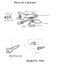
1. Use the illustration provided to review the parts of a rocket. You may wish to use an assembled model as part of this review.
2. Do a static test so that the students can see the workings of the engine and the recovery system. See Lesson #'s 12 or 36 for a review of how to set this up.
3. Have the students review the principles of flight for the rocket. Bernoulli‘s principle may not be as obvious for the rocket as it was for the plane. Newton's laws are a bit more obvious.
4. Have the students assemble their models after reading the directions through carefully.
5. Test the rockets for stability. First locate the center of balance by resting the body tube of the completed model on your finger. Next, tie a loop of string around the balance point and tape it down. In an open area, swing the model around by the string. If the model is stable, it should fly without tumbling. If the model does tumble, add weight to the nose cone or use larger fins. (This should not be a problem with the models from a kit.) D0 NOT FLY A MODEL THAT DOES NOT PASS THE STABILITY TEST.
6. Paint the models and allow them to dry. This adds to the durability of the rocket which should last for many launches. 7. Have the students decide how to evaluate the flight of the rocket. How high did it fly? How fast did it go?
How close to a point which has been predetermined can you get the model to land? '
Extensions: Contact a local amateur rocket club and arrange for a demonstration of larger rockets which these clubs many times make. Have the students build one or more class rockets of the larger variety. Have the students build and test a rocket of their own design.
Find out about the manufacture of safe model rocket engines. (The substance in the manufactured model engines is identical to the solid fuel in the boosters used by the Shuttle).
10. ROCKET NOZZLES
SUBJECT:
Science
GRADE:
7,8,9
GROUP SIZE:
Small TIME;
2 45-minute periods
TYPE OF ACTIVITY:
Student Investigation or Teacher Demo
TEACHING STRATEGY:
Expository Guided Discovery
CONCEPTS:
Thrust Velocity RPM Venturi
SKILLS:
Construction Collecting and Interpreting Data
Objective: To have students investigate, using a funnel, the effects of a decreasing diameter in a nozzle on the velocity of air passing through it.
Materials: 4 - 7 oz. Styrofoam cups; 3 - 8 1/2" x 11" sheets of paper; scissors; masking tape; single edge razor blade or utility knife; 2 - aluminum pie plates, the throw away kind; ruler; pencil; magic marker; 1 small finishing nail; 1 T pin; 1 coat hanger; 1 stick 1/4 x 1 x 10 - a paint stirrer works well; 1 or 2 small buttons; an air source - a vacuum that can be hooked up to blow is fine.
Procedure:
Construct four funnels and two pinwheels using the above materials, as follows:
- Cut the bottoms out of the Styrofoam cups using the razor blade.
- Roll the sheets of paper into funnels; tape them securely with masking tape and insert into each of three of the cups; tape the funnels to the cups.
- Cut each funnel in turn to produce openings of 1 cm, 2 cm, and 4 cm respectively. The fourth cup should have an opening of 5 cm and will be used without a paper funnel.
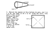
- Measure two squares on the aluminum pie pans, one 6 cm x 6 cm, the other 12 cm x 12 cm. Using the ruler, draw pencil lines corner to corner on each square. Make a small hole in the center where the lines cross. Cut in from the corners, to within 1 cm of the center hole.
- Make small holes in the corners as shown in the diagram. Bend the corner with the hole into the center and pin the pinwheel to the stick making sure to put a small button between the pinwheel and the stick. (This will allow the wheel to turn freely). Repeat this procedure with the large pinwheel and mount it on the coat hanger. (You can tape the pin to the coat hanger).
- Paint one fin of each pinwheel with the magic marker to better keep track of rotations.
- Insert the air hose into each nozzle from the wide end and direct the airflow toward each pinwheel.
- Have the students observe the rotation speed of each pinwheel when acted upon by each funnel nozzle. Have the students try different distances from the pinwheels but make sure they control this variable for their final data collection.
Discuss the data collected with the students. What happened to the RPM’s of the pinwheel when the funnel openings got smaller? Were these results the same when the pinwheel size changed? What was the difference, if any, between the pinwheels? How did a change in distance from the nozzle to the pinwheel effect the RPM's?
Note: Nozzles are thermodynamic devices for converting pressure into velocity according to Bernoulli's equation:
- pressure energy + velocity energy = constant.
Therefore as pressure increases, velocity must also increase. The smaller nozzle creates higher pressure inside the funnel and therefore higher velocity of the air flowing through it. Remember your air source is constant. Of course, this is how great velocities are achieved in a rocket engine nozzle.
Extension: Have the students compute the size ratio of the pinwheels and the nozzles from largest to smallest.
(5 to 1 for the nozzles) (2 to 1 for the pinwheels). Can the students predict from their data what the next size of pinwheel or nozzle will produce in terms of RPM?
References: Ned Hannum, NASA, Cleveland, Ohio Bruce Wilms, Chesterland, Ohio
11. EASY AS 1-2-3
SUBJECT:
Science
GRADE:
7.8.9
GROUP SIZE:
Large or Small
TIME:
60 minute period
TYPE OF ACTIVITY:
Student Investigation or Teacher Demo
TEACHING STRATEGY:
Guided Discovery
CONCEPTS:
Newton's Three Laws - Inertia, Acceleration, Action/Reaction
SKILLS:
Observation Collecting and Interpreting Data
Objective: To learn and experience examples of Newton's three laws of motion.
Materials: Marble or other small sphere; two meter sticks taped together in a "v" shape; three spring scales; plastic cup; index card; coin; stop watch.
Teacher Background Information: An understanding of the motion of planes and rockets requires a general knowledge of Newton's three laws. The following activities are specific to each of the laws and will help the student see relationships among all three.
Procedure:
Newton's First Law... Generally stated as, “Things in motion tend to remain in motion, things at rest tend to remain at rest." The tendency to stay at rest or, once moving, in motion is called INERTIA. Things move or stop only if acted upon by another force. To demonstrate:
- Set a container on a table.
- Place a card on top of the container and place a quarter on top of the card.
- Flick the card away with your finger.
- Did the coin have inertia? What force acted on the card to set it in motion? What force acted on the coin after step 3? (If the card is flipped out of the way fast enough the coin will remain over the container and fall into it.)
Newton's Second Law... "Acceleration of an object increases as the force causing acceleration increases."
- Prepare a ramp for a marble or other sphere about 1 meter long.
- Lift one end of the ramp and place a pencil under it.
- Roll a marble down the ramp and time the roll from one end to the other.
- Lift the ramp higher. Place a book under the lifted end and repeat step 1.
- Start the marble on a ramp with one end pencil high. As the marble starts out, lift the end of the ramp higher. What was the effect on the speed of the marble?
- Compare the results of the first two experiments. What was the result? What was the force that was acting on the marble? How was it increased? What was the effect of this increase?
Newton's Third law... “For every action there is an opposite and equal reaction."
- Take two spring scales and hook them together.
- Have two students pull on the scales in opposite directions. Record the readings from both scales.
- Place a third scale between the other two. Record the readings from all three. What were the differences in the readings for the two scales? When three scales were used? (The readings should all be the same in each experiment.)
Extensions: Have the students apply the principles of Newton's laws to the description of
- A plane taking off and climbing to 2000 feet while accelerating to 120 miles per hour.
- A three stage rocket launched into orbit around the Earth then sent on to the moon. Which of Newton's laws are being applied in each case and at what point are they being applied?
12. CONSTRUCTING A "THRUSTOMETER"
SUBJECT:
Science
GRADE:
7,8,9
GROUP SIZE:
Small or Large
TIME:
2-60 minute periods
TYPE OF ACTIVITY:
Student Investigation or Teacher Demo.
TEACHING STRATEGY:
Expository Guided Discovery
CONCEPTS:
Thrust, Power Curve, Action/Reaction
SKILLS:
Measurement Interpreting Data Experimentation
Objective: To help students understand the difference in thrust power by constructing a device to measure thrust.
Materials: three 2 x 4's (for base and swinging arm); one piece of pressed board or plywood for upright; small piece of wood for stopper; 4 brackets; small piece of wood to block front of engine; bolt; 4 washers; 2 nuts; wire; drill; graph paper; bricks; various size model rocket engines.
Procedure:
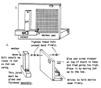
In order to answer questions about how much thrust a particular rocket engine has, the students can construct a device that will measure various engines for model rockets. The first diagram shows what a homemade "thrustometer" looks like. and the second diagram shows how to make one:
Note that the 2 x 4 is free swinging on a bolt fastened securely to the plywood back.
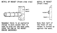
The rocket holder must also be firmly constructed and attached. Look at these sketches and be sure you understand the need for each part of this rocket holder.
Attach a sheet of graph paper and a marker pen to the thrustometer and move the swinging 2 x 4 to see if the pen moved smoothly and if the graph paper is properly placed. When all is ready, attach a small engine securely in the rocket holder and get students a safe distance away. Then field test the thrustometer.
If the 2 x 4 arm doesn't move, the wood is too heavy for the engines. If it quickly swings to the stopper, then there isn’t enough weight on the arm. What is needed for the arm is an optimum weight so that a small engine will move it a little and a big engine wi11 move it close to the top.
Once you have found the proper weight for the arm, set off several model rocket engines and calibrate the amount of thrust as shown on your graph paper.
13. RECOVERING SPACECRAFT WITH PARACHUTES
SUBJECT:
Science
GRADE:
7,8,9
GROUP SIZE:
Individual and Large
TIME:
2-45 minute periods
TYPE OF ACTIVITY:
Student Investigation
TEACHING STRATEGY:
Guided Discovery
CONCEPTS:
Deceleration Braking
SKILLS:
Modeling Recording Data Interpreting Data
Objective: To demonstrate that the parachute system used is dependent upon the weight of the vehicle.
Materials: Set of gram weights up to one gram (washers may be substituted); three pieces of cloth one foot square; ball of string; scissors; ruler.
Teacher Background Information:
Spacecraft orbiting the earth are returned by means of braking rockets or retro-rockets which are fired in a forward direction and thus slow the craft down counteracting the inertial movement away from the Earth. The Apollo spacecraft did not use retro-rockets, however. Parachutes were used at the proper time to slow the descent. Scientists are also experimenting with paragliders and parachutes to return parts of spacecraft to earth and to land on other planets.
Procedure:
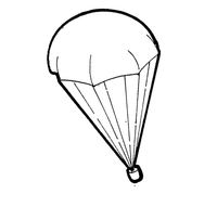
Have the students make octagons out of the three pieces of cloth. This can be done by cutting four triangles off the corners, 3" x 3". For easier identification, have the students mark the pieces of cloth in the middle with a red marker, indicating the weight attached as follows: "1/4," "1/2," and "1." Have them tie a 12" piece of string to each of the eight corners of the octagons. Tape the ends of the eight strings together on the one marked "1/4" and attach a one-quarter gram weight to the parachute and fold it neatly. Repeat with the one-half and the one gram parachutes and weights.
Go outside and drop the one-quarter weight parachute from a measured height. Have students record the time it takes for the parachute to descend. Repeat twice for an average and then do the same with the one-half gram and the one gram weighted parachute. Once your students have the data, go back to the classroom and discuss:
- What did the students observe about the velocity with which the weights returned to earth?
- As the weight of the vehicle increases, how must the parachute system change?
- Can the size of the chute be increased forever? Explain.
- Did the parachutes return to the same place each time? What force acts on a parachute that makes its destination difficult to predict?
Adapted from educational materials available from NASA Kennedy Space Center Teacher Resource Room
14. RECOVERING SPACECRAFT WITH PARAGLIDERS
SUBJECT:
Science
GRADE:
7,8,9
GROUP SIZE:
Individual and Large
TIME:
2-45 minute periods
TYPE OF ACTIVITY:
Student Investigation
TEACHING STRATEGY:
Guided Discovery
CONCEPTS:
Lifting Body Descent
SKILLS:
Modeling Experimenting
Collecting Data
Objective: To demonstrate the way paragliders work.
Materials: Three 1/4" dowels 12 inches long; heavy tissue paper or wrapping paper; tape; scissors; knife; electric drill with a 1/8" or 1/16" bit.
Teacher Background Information:
Parachutes have been used in the recovery of manned spacecraft and to slow jets landing at high speeds. The parachute systems for recovering space vehicles have been very workable but parachutes do present the problem of maneuverability. NASA has been experimenting with a paraglider which would be maneuverable and create lift. This device could be used to land space vehicles at a predetermined area.
Procedure:
Using the drill, make a small hole in one end of each dowel, about 1/2" from the end. Using the knife, taper the ends with the holes in them. Tie the three ends together so they form a fan shape. Cut pieces of the paper to fasten over the dowels, making sure you allow some slack so the glider has two billowing sections. Tie a string to the end of each dowel and one to the front section so a weight can be tied to the strings.
Take the class outside and experiment with various weights tied to the paraglider. How much weight can it hold and still provide a safe descent? Have students discuss what variables have to be considered in constructing a paraglider.
Extension: Ask the students to construct a paraglider capable of returning an egg to the ground safely from a 30 foot height with little or no protective wrapping around the egg.
Adapted from educational materials available from NASA Kennedy Space Center Teacher Resource Room
15. WIRING A LAUNCH SYSTEM
SUBJECT:
Science
GRADE:
7,8,9
GROUP SIZE:
Small
TIME:
Several 45 minute periods TYPE OF ACTIVITY;
Student Activity
TEACHING STRATEGY:
Guided Discovery Expository
CONCEPTS:
Circuitry, Remote Control
SKILLS:
Construction Reading and Interpreting Diagrams
Objective: To apply basic circuitry concepts to the production of a practical, electrically controlled launch system for model rockets.
Materials: (For each system to be wired) several feet of bell wire; electrical tape; two alligator clips (small); two - 6 volt light bulbs; two light bulb holders; 2 toggle switches or one toggle and a push button type switch; wood to construct a box to hold the wiring or an electrical hobby box of the type available at an electronics supply store; screwdriver; wire strippers; (optional) soldering gun and solder.
Procedure:
You may proceed in one of two ways for this activity, depending on time and how open-ended you wish to be.
1 Have the students investigate the requirements of a launch circuit and the availability of diagrams which may help them. A source may be a local model rocket club, a company that produces models such as estesrockets.com or a local hobby shop.
1 Use the diagram which follows this lesson plan.
2. Have the students interpret the diagrams to produce their circuit.
3. Test the circuits and use to actually launch a model produced in lesson # 9.
4. Have the students discuss the need for the safety features found in most circuits and have them build one into their own if they have not.
Extensions: Have the students find and report on information about the actual launch control systems used by NASA. If you have a science club or a group of advanced students, they may wish to investigate and build a remote, perhaps radio-controlled launch system.
16. MODEL ROCKET CONTEST
SUBJECT:
Science
GRADE:
7.8.9
GROUP SIZE:
Large
TIME:
% DAY
TYPE OF ACTIVITY:
Game Simulation
TEACHING STRATEGY:
Expository Guided Discovery
CONCEPTS:
Launch Safety, Altitude, Trajectory
SKILLS:
Control of Variables Following Directions
Objectives: To apply skills and concepts learned about rocket flight to the solution of a specific challenge in a model rocket contest; to apply the safety rules of model rocket flying during actual launches; to apply the concept of Control Of Variables to achieve an approximation of a specific objective with a model rocket.
Materials: Students with model rockets; a launch system for every 5 to 10 students; tape measure; two or three red flags and stakes to nail them to; stop watch; data scoring sheet; a big field and a nice day.
Teacher Background Information:
A FUN culmination to the building and testing of models is to actually fly them. A contest with specific tasks to prepare for is a way to have students "put it all together". The following rules and contest descriptions are just two of several ideas for rocket competition. If you want more information, the Estes company in Penrose, Colorado has a booklet, contest forms and award certificates available. If you have Science Olympics in your area, the directors may have suggested rules for competition. You may wish to use the school competition as a way to prepare for a larger meet between schools from many areas. A model rocket group in your area may be willing to assist you.
Procedure:
The rocket contest will consist of two events. Individuals or teams may enter one or both events.
A TEAM may consist of no more than FOUR contestants. The winning team score for any event shall be the sum of the points for each individual launch. Team members must launch two rockets within the launch window provided for them during the contest. If a team member's rocket fails to launch after two tries the rocket will be disqualified. Another rocket may not be substituted. A team may enter one or both events.
AN INDIVIDUAL may enter one or both events. Awards will be made for each event. An individual's rocket will be disqualified if it fails to achieve launch after two tries.
ALL TEAMS AND OR INDIVIDUALS MUST REGISTER FOR THE ROCKET COMPETITION PRIOR TO THE DAY OF COMPETITION so that launch planning can take place.
General Information
- All model rockets entered in the events will be subjected to a safety inspection prior to launch.
- Only standard model rocket engines will be allowed. No engine larger than a Series DQ may be used.
- All launchings shall be made using electrically operated igniters.
- Only safe recovery systems will be allowed on the rockets. Safe recovery includes PARACHUTE, GLIDER, TUMBLE, and STREAMER type recovery. Any deviation from these standards will result in the automatic disqualification of the contestant.
- All launches will be made from a standard launch platform. The launch rod will be 1/8 inch in diameter, 36 inches in length.
- The launches will be made outdoors. In the event of rain the contest will be delayed or canceled.
No launches will be made if the wind speed exceeds 12 kilometers per hour
THE CONTESTS
1. DRAG RACE
In this event a model rocket is launched which has been designed to:
- a. achieve flight
- b. deploy a recovery system and...
- c. land in the shortest time possible.
Remember a safe recovery system must be used. Points will be awarded for each second of flight beginning with ignition and ending on impact. The lowest score wins. In the event of a tie, additional points will be subtracted for good design and creativity.
2. SPOT LANDING
A selected landing point somewhere within a radius of 10 meters of the launch site will be marked with a flag. The winner will be the rocket which lands the closest to the flag. In the event of a tie, additional points will be awarded to the rocket which achieves the greatest time aloft and for design.
- a. Safe recovery systems must be used. The recovery system must have deployed before descending below 15 meters.
- b. The launch rod may not be adjusted to an angle of more than 25 degrees from the vertical.
17. BE COOL
SUBJECT:
Science
GRADE:
7,8,9
GROUP SIZE:
Large
TIME:
45 minutes
TYPE OF ACTIVITY:
Teacher Demonstration
TEACHING STRATEGY:
Guided Discovery
CONCEPTS:
Ablation Regenerative cooling
SKILLS:
Observation Inference
Objectives: To demonstrate methods of cooling a spacecraft or aircraft traveling at high speed in the atmosphere; to learn the concepts of regenerative and ablation cooling.
Materials: Two ring stands or tripod supports; two burner triangles; two small paper cups; two candles; water; heavy plastic cup; plastic cup which has been dipped in melted wax repeatedly until a thick (1/2" or more) coat of wax has built up on the outside; matches.
Teacher Background Information:
The problem of dissipating the heat build-up caused by friction when a plane or spacecraft travels through the atmosphere has been a hard one to solve. Three main ways of cooling are used now. One is ablation. Ablation makes use of a melt away covering to carry the heat away with it. The covering is sacrificed and enough must be put on a craft so that it does not all melt before the craft slows to a speed where heat is no longer a problem. This cooling technique was used on spacecraft through the Apollo missions.
Another technique is that of regenerative cooling. This method makes use of a super cooled fluid passing through pipes near the surface which is being heated. The fluid absorbs the heat and carries it away from the surface. This method is used in some planes and in many rocket engines where the fuel, liquid Oxygen and/or Hydrogen, is circulated around the rocket nozzle and preheated before being burned. The third method uses material which actually stores the heat and releases it slowly so that nearby surfaces do not overheat quickly. The Space Shuttle uses such a material. '
Procedure:
- 1. Set up two ring stands or tripods and place a triangle on each ring. Place a candle under each. Fill one paper cup and place it on one of the stands, above the candle. Place an empty cup above the other candle. Light the candles. What did you observe happen? Why do you suppose that is? (The empty cup will burn quickly. The filled cup will not get hot enough to ignite because the water carries the heat away or stores the heat.) This is similar to the Shuttle tile function.
- 2. Take another cup and place a small amount of water in the bottom or fold an index card into a flat tray shape with a small amount of water in the tray. Heat the cup or card the same way as before. The water will boil carrying the heat away in the steam. Of course, the card will not ignite until the water has all been evaporated. This is an example of regenerative cooling.
- 3. Hold the wax covered cup up with a stick over a plate. Light one of the candles or a propane torch. Aim the flame at the cup and observe. What happens? Why do you suppose the cup behaved the way it did? (The wax melts away carrying the heat with it.) If you try a control experiment with an uncovered cup, what do you suppose will happen? Try the same experiment with the heavy plastic cup. What similarities or differences were there between this cup and the wax coated cup? USE A WELL VENTILATED AREA. This is an example of ablation.
Extensions:
Try to obtain other materials which will respond to ablation. A chemistry teacher may be able to suggest some plastics or other substances which will work. It is very difficult to get a sample of a Shuttle tile but you might try. The Space Mobile demonstrators bring a piece with them when they visit schools for workshops; you may be able to see a demonstration of the tile's ability if you have such a visit. The tiles, by the way, must be cooled by air conditioning within 15 minutes of touchdown or the heat "soaks" through to the Shuttle skin which is only aluminum.
18. SATELLITES IN ORBIT
SUBJECT:
Science
GRADE:
7,8,9
GROUP SIZE:
Small
TIME:
50 minutes
TYPE OF ACTIVITY:
Student Investigation
TEACHING STRATEGY:
Guided Discovery
CONCEPTS:
Orbit Inertia Gravity
SKILLS:
Observation Interpreting Data
Objective: To demonstrate two forces acting on a satellite.
Materials: Five metal washers; 40" length of string; large wooden spool.
Teacher Background Information:
A satellite remains in its orbit because of two physical phenomena: inertia and gravity. Inertia is the tendency of a moving body to continue to move in a straight line unless something interferes to change its motion. Gravity pulls a spacecraft into orbit around the Earth. Satellites are not slowed by friction because there is almost no atmosphere to cause friction in space.
Procedure:
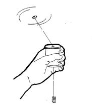
- Push the string through the hole in the spool. Tie four of the washers to one end of the string and tie one washer to the other end.
- Ask the class to observe what happens when you hold the spool in your hand and whirl the single washer in a circle. (The four washers should hang down from the bottom of the spool.)
- Ask the students why this happens? (The weight of the four washers and the string connecting them with the single washer prevent the single washer from flying off in a straight line as it circles.)
- Ask the class to determine what the single washer represents (an orbiting satellite) and what the string represents (the gravitational pull of the Earth).
- Ask what would happen if the single washer were able to fly loose from the string? (It would fly out and away in a straight line.)
- Ask why a spacecraft does not fly straight into space? (Because of the Law of Gravitation plus retrorockets, attitude thrusters and navigational devices using the laws of motion.)
- Ask students to think about why satellites do not slow down and stop? What happens when students run and slide on the ice? What happens when they throw a ball? What is it that causes the skater and the ball to slow down? (Friction) Why doesn't the satellite slow down? (In space there is very little for a satellite to rub against since space is almost empty.)
Extension:
For further demonstrations of the everyday experiences which might illustrate straight line inertia of motion ask your students to think about how water is thrown off the wheels of a passing automobile. To demonstrate, stand a bicycle upside down and have a student turn one of the wheels while another pours a few drops of water onto the tire. You can also lay the bicycle on its side and lay small objects on the sidewall of one tire. (Make sure they are small and soft, like an eraser, for example.) Spin the wheel and the objects fly off in a straight line. Ask your students what they think may cause that to happen.
19. OVAL ORBITS
SUBJECT: Science
GRADE:
7,8,9
GROUP SIZE:
Small
TIME:
50 minutes
TYPE OF ACTIVITY:
Student Investigation
TEACHING STRATEGY:
Guided Discovery
CONCEPTS:
Orbit Angle of Insertion Apogee Perigee
SKILLS:
Observation Interpreting Data Experimentation
Objective: To introduce the concept of orbit and to observe that objects can orbit in both oval and circular orbits.
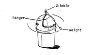
Materials: Basketball; coat hanger; tape; two or three feet of string; weight (lead sinker works well); pail; thimble; softball.
Teacher Background Information: Most earth satellites have orbits which are oval shaped. The oval pattern is determined by the angle of insertion into space. The point farthest from the earth is called apogee. The point in the orbit nearest to the earth is called perigee.
Procedure:
Before class period, place the basketball in the pail; bend the coat hanger and tape it to the ball so that it is in an upright position. Attach the string to the thimble and place it on top of the upright hanger. Attach the weight to the other end of the string.
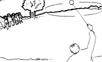
When the class arrives, get the softball and take the students outside. Standing at a marked line, have a student toss the ball out gently. Mark the spot where it lands. Have another student throw it out a little harder and mark the landing spot. Last, have someone throw the ball as hard as he/she can and mark the spot where the ball lands.
Ask the students to speculate about whether anyone could throw a ball hard enough so it would fall over the horizon and miss the earth altogether. Ask the group to think about such things as "Why spacecraft have to be launched with more powerful launch systems in order to reach orbit in space as opposed to suborbital flights",or “What sort of orbital configuration do spacecraft fly in as they orbit?"
When the class is back in the classroom, explain to them that the ball in the bucket represents the earth and the weight represents a satellite. Ask a student to tap the weight away from the ball and observe how and where it turns. Have the student carefully push the weight away at different angles. At different speeds. While it is in motion, what does the student notice? Are there differences in the shapes of the orbits? Are some elliptical? Circular? How can the type of orbit be determined? Discuss apogee and perigee with the students. Explain the smallest distance the weight (satellite) is from the ball (earth) is called perigee of the orbit and the farthest distance is called the apogee.
Give each of the students the chance to experiment with the ball and the weight. By the end of the lesson, the students should be able to address these questions:
- How is the type of orbit determined? (By the angle of insertion and speed.)
- What kind of orbit occurs when the weight is pushed out from the surface of the ball? (An elliptical orbit)
- What must be done to achieve a circular orbit? (Tap the weight away from the ball and then tap again or start the orbit with the weight already away from the ball.)
- What is the farthest distance the satellite orbits from the earth called? (apogee)
- What is the shortest distance the satellite orbits from the earth called? (perigee)
Extensions: Have the students do the experiments in the next activity to explore circular orbits further and to explore the effects of gravity and inertia on orbits.
Adapted from educational materials available from NASA Kennedy Space Center Teacher Resource Room 88
20. INERTIA & GRAVITY - CIRCULAR ORBITS
SUBJECT:
Science
GRADE:
7,8,9
GROUP SIZE:
Small
TIME:
50 minutes
TYPE OF ACTIVITY:
Student Investigation
TEACHING STRATEGY:
Guided Discovery
CONCEPTS:
Orbit Inertia Gravity
SKILLS:
Observation Experimentation
Objectives: To explore the forces necessary to achieve a circular orbit using a model; to learn in what direction, relative to gravity, inertial force must be applied to achieve a circular orbit.
Materials: Two ropes or cords about 2-3 meters long; a box or chair; the basketball set up from the Oval Orbits activity # 19.
Teacher Background Information:
To achieve a true circular orbit, a space vehicle after launch must use rocket thrust aimed at right angles to the center of gravity of the earth. The following activity demonstrates the phenomena in two ways: first, using a demonstration with two ropes and a weighted box or a chair and, second, with the basketball and string set-up from the previous activity.
Procedure:
- Tie two ropes to a box or chair.
- Have two students hold the ends of the ropes and move away from the box or chair at right angles to each other.
- Have the two pupils pull straight back slowly on the ropes. Note the direction the box or chair travels relative to the students.
- Have one student, and then the other, pull harder on their ropes. How is the direction of the box or chair changed?
- Try angles other than 90° and note the angle of the path the box or chair takes. Explain to the students that one rope represents gravity and the other rope represents inertia from the rocket.
NOTE: To achieve a specific direction somewhere between the direction of thrust and the direction of gravity the two must be at right angles. Too small an angle will result in a trajectory which will carry the satellite (box or chair) back to earth. Too great an angle will result in the satellite losing speed and then falling back to earth unless it can achieve enough speed (40,000 kph) to break away from gravity. - Using the basketball set-up from the previous activity, "Oval Orbits," have the students explore what is necessary to achieve a circular or near circular orbit with the weight.
- Have them tap the weight into an elliptical orbit and tap again at right angles to the ball.
- Try other angles and observe the results.
Extension:
Investigate orbital and escape velocities. Have students note how much inertia an object must have to achieve orbit. How fast must it go to break away from orbit all together?
THE FOLLOWING DEMONSTRATION SHOULD ONLY BE DONE IN A LARGE AREA SUCH AS A PLAYGROUND.
Have the students tie a 2 meter long thread around a mushball or other heavy soft ball. Use light thread as you want it to break. Have a student stand well away from any other students or buildings and swing the ball around him/her to achieve orbit. Have the student swing faster until the ball (spacecraft) breaks the string (gravity.) Observe the path the ball takes once it has broken “the pull of gravity."
Remember, keep the students back far enough so that the ball hits the ground first before it can be caught.
How is the ball and string like a spacecraft and gravity? What was necessary to "break" the pull of gravity?
21. "G" WIZZ
SUBJECT:
Science
GRADE:
7,8,9
GROUP SIZE:
Small _
TIME:
45 minutes
TYPE OF ACTIVITY:
Student Investigation
TEACHING STRATEGY:
Guided Discovery
CONCEPTS:
Weight Mass
SKILLS:
Construction Collecting and Interpreting Data
Objectives: To distinguish between weight and mass; to develop techniques of finding mass when there is no weight; to build equipment to determine mass when a balance will not work.
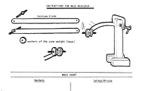
Materials: For each group of three students: 1 hacksaw blade; 1 small "c" clamp; 1 small bolt with two nuts to fit the hole at the end of the hacksaw blade; several washers of the same mass; a stop watch; data sheet; a table or chair to fasten the "c" clamp to:(You can build a stand as in the diagram and weight it with bricks).
Teacher Background Information:
The weight of an object is a ways a measure of the pull of gravity on that object (the attraction of one mass to another). On the Moon, objects weigh 1/6 of what they do on the Earth. In space, some 300 kilometers above the Earth, objects weigh about 1/3000 of what they do on the surface. (Essentially, they are nearly weightless.) A 210 pound astronaut would weigh about 1 ounce. Many of the experiments done on the health of astronauts required finding their mass while in space. Mass is measured in grams. Grams are defined as the mass of one cubic centimeter of water. You are measuring the amount of matter in a given space when you measure mass. The amount of astronaut does not change while in space from that while on the Earth or on the Moon. His or her mass would be the same - only the weight (attraction of gravity) would change. So, how can mass be measured when there is no weight???
Procedure:
- Attach a hacksaw blade to the leg of a chair or a stable platform of some kind with a "c" clamp.
- Fit a bolt through the hole at the opposite end of the blade and secure it with a nut.
- Attach a washer to the bolt and secure it with the other nut.
- Pull the blade to one side and release.
- Have a student count the number of oscillations of the blade while another student keeps time with a stopwatch.
- Have another student keep track of the swings per minute on the data sheet.
- Add washers to the blade, one at a time until several bits of data have been collected.
- Make a calibration chart of the results by graphing the data.
Note: The hacksaw blade oscillations are independent of gravity and are dependent on the elasticity of the metal. The same number of swings would be recorded on the Moon or in space. FIND THE MASS OF AN UNKNOWN. - Place a small ball of clay on the mass tester.
- Measure the number of swings per minute and refer to the calibration chart to determine the mass in washers.
- Find the mass of the washers and compute the mass of the clay in grams.
- Place the clay on a balance and check your calculations to see how accurate your measurements were.
Note to the Teacher: You may wish to tie this lesson in with one on the arbitrary nature of systems of measurement.
Extensions: The astronauts use a device similar in operation to the simple device the students produce in this lesson to measure their mass in space. Have the students find out more about it by investigating some of the experiments performed on Skylab.
22. NAVIGATING IN SPACE
SUBJECT:
Science
GRADE:
7,8,9
GROUP SIZE:
Small
TIME:
3 45 minute periods
TYPE OF ACTIVITY:
Student Investigation
TEACHING STRATEGY:
Guided Discovery
CONCEPTS:
Magnetic Field Tracking Frame of Reference
SKILLS:
Observation Inference Recording Data Experimentation
Objectives: To help students understand the difficulty of conventional reference points in navigating in space; to understand how the earth's magnetic field can be used to orient satellites in space; to illustrate how tracking stations can locate a satellite in space.
Materials:
- For Activity 1 - The Problem - Thread or string, paper stars (stickers are easy); tape or tacks; shoe box; paper; pencil.
- For Activity 2 - The Solution - Bar magnet; dry cell battery; paper; light or bell; iron filings; compass; copper wire.
- For Activity 3 - Another Solution - Portable radio.
Teacher Background Information:
Tracking provides information by continuously reporting the location of a satellite, a probe that is going deep into interplanetary space, or of small rockets that will penetrate space on an up-down path of, perhaps, only a few hundred miles. Location is important for the scientist-experimenter because he/she has to know precisely where the spacecraft is at a particular point in time so an event measured by the spacecraft can be correlated, for example, to its position to the Sun, the Moon, or Earth. The scientist has to know its position to send it guidance information, to send it commands to make observations and to transmit data or change flight plans.
Long range rockets have guidance systems which work on the principle of comparing present position with point of destination. In traveling to the moon the astronauts have to navigate by using the Earth and the Moon as frames of reference. Tracking stations can also locate a satellite exactly.
Procedure:
Activity 1
The first activity should help to orient the pupils to the problems of space navigation.
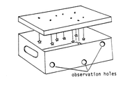
- Before class, suspend thread from the top of the shoe box. Hang the paper stars on the end of the threads. Hang them in such a way as to take on the shape of the Big Dipper and place the cover on the box. Make several holes in the sides of the box for the students to look through. In addition, cut a hole for more light to enter the box in one end. (See illustration, top of next page.)
- Ask the students to look through one of the holes. In what position are the stars? Have students sketch their position on a piece of paper.
- Have the students move. What do they observe now? Re-sketch the stars.
- Why doesn't the Dipper have its familiar shape when observed through the holes? Discuss the notion that when we travel in space the appearance of the constellations will be different. This will affect an astronaut's bearings on direction when flights to the planets become a reality. Make certain students understand the appearance of the constellations in space depends upon the position that they are viewed from. (You can demonstrate the same thing by hanging string, with stars attached, from the ceiling of your classroom and having the students move about the room noting the difference in configuration from where they happen to be observing.)
- Encourage pupils to experiment with frames of reference such as: throwing the ball to someone who is running, plotting the paths of a child on a Ferris wheel as seen by friends on the ground, friends on the wheel and the child herself, etc.
Activity 2
- Have a student place a magnet under a piece of paper and sprinkle iron filings evenly over the paper.
- Have student gently tap the paper until the filings form a pattern over the magnet. Have another student hold a small compass over the pattern and observe where the needle points in relation to the lines of force. Where does it point? How does this help to orient a satellite? If we put a magnet in a small satellite near the earth, we could point it in outer space. How? To see how, set up the following apparatus: Attach a large dry cell battery (six volt) by a coiled copper wire to a light bulb or doorbell. Move a compass up to and through the coil to see where the needle points.
With a current loop around the base of a Tiros satellite, space scientists can point or orient it in outer space.
Activity 3
- Have a pupil turn on the transistor radio and tune it in on a station. Turn the radio around and listen to the strength of the signal received.
- Change the direction of the radio. Discuss the relationship between the location of the radio station and direction of the transistor radio. How are radio transmitters on a satellite used to aid in locating and tracking a satellite?
Extension: Have the students research the global system of tracking stations and communications networks.
Have a "ham" radio operator in to tell the class about monitoring satellites and talking to astronauts in space.
Adapted from educational materials available from NASA Kennedy Space Center Teacher Resource Room
23. ROVE, ROVE, ROVE THE MOON...
SUBJECT:
Science
GRADE:
7,8,9
GROUP SIZE:
Small or Large
TIME:
45 minutes
TYPE OF ACTIVITY:
Student Investigation
TEACHING STRATEGY:
Guided Discovery
CONCEPTS:
Traction Surface Conditions Lunar Rover
SKILLS:
Experimentation Collecting Data Modeling
Objectives: To help students understand the problem of getting people around on a loose surface such as the Moon's; to apply that understanding to the construction of a land rover.
Materials: LONG cardboard box filled with dry, fine sand; Wooden plank; Toy car.
Teacher Background Information:
The moon rover, that dune-buggy, electric car that astronauts used on the moon, provides great motivation for students to explore the question of transportation on the surface of the Moon. If you ask students the question, "What would it be like to live on the Moon?" one of the responses would likely involve intra-moon transportation systems. And, as we live in a car society of self-contained, self-powered vehicles, capable of going anywhere at the driver‘s whim, the car might very well be the most common image in students' minds. This concept and this interest can lead to all sorts of experimentation and quantitative data collection.
Procedure:
Set up the long cardboard box with the dry sand.
Ask the students to observe what happens when you send a toy car down the plank onto the surface of the sand. Ask them to describe what they know of the Moon‘s surface and how the astronauts overcame the problem of the loose surface.
- Instruct the students to break up into small groups of 3 or so to discuss what sort of rover they could construct that would move over the loose sand with ease. Explain they will be asked to place their "rover" on the end of the wooden plank and to measure the distance the device moves across the sand.
- Give the groups a few days to work out what they want to do and time to construct the rover. See if any of the groups ask to test the rover in your sand. If they ask, of course, let them!
- On the appointed day, have students bring in their rovers, set up the experiment and ask each group to run their rovers.
- Collect the measurements and graph the results.
Discuss with the class how each of the groups went about solving their problem. How did they arrive at consensus for the final vehicle? Did they pre-test before the big day? Did they have to rework any ideas?
Extension:
Have the students discuss the idea of mass transit on the Moon. How might they go about adapting some of the vehicles they came up with? Why might it be very important to have mass transit rather than, or along with, "cars" that move people a few at a time?
As they visualize a moon colony, what does it look like, as far as transportation goes? What are some of the particular reasons for specific kinds of transportation on the moon colony? Are there any kinds of transportation they might need on the Moon that we don't necessarily need here on Earth?
2011.12.31 - accessed 737 times , 2012.12.24 - 2717 , 2013.8.20 - 3,727
